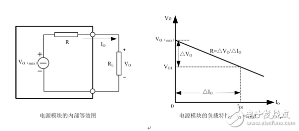
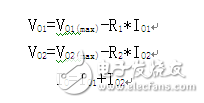
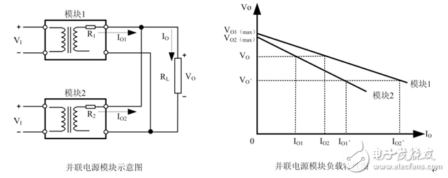
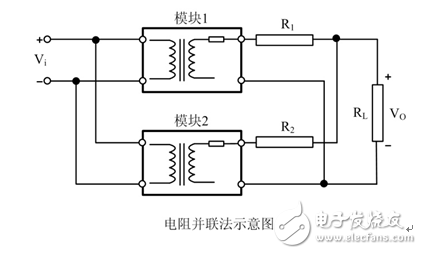
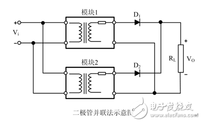
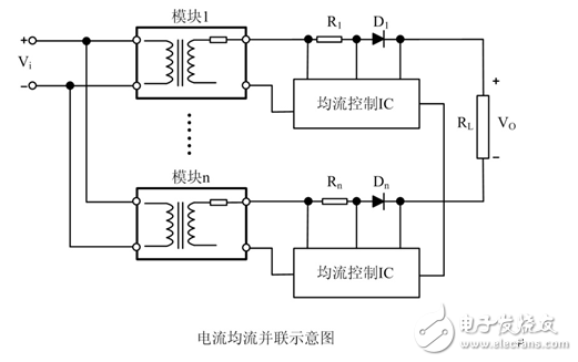
1. Roots that cannot be connected in parallel When many engineers just touch the circuit system design, they will always use multiple power modules in parallel, which will result in the module output not being evenly distributed, which will cause the module output to be short-circuited, abnormally activated, and damaged. To completely solve the problem of parallel current sharing in parallel modules, we must start with the structure and output characteristics of the module to find the root cause. figure 1 Figure 1 shows the internal equivalent and output load characteristics of the power module: V0=f(I0), R is the output impedance of the module (including wire resistance and contact resistance, etc.). At no load, the module output voltage is the maximum value V0 ( Max). When the load current changes ΔI0, the load voltage change amount is ΔV0, ΔV0=R*ΔI0, and R*ΔI0 also indicates the load regulation ratio of the module. The relationship between the load voltage V0 and the load current I0 can be expressed as: When the two modules are connected in parallel, as shown in Figure 2, there are: If the parameters of the two modules are identical, ie: V01(max)= V02(max), R1=R2, the two load characteristic curves coincide, and the load current can be evenly distributed. However, in practical applications, the parameters of V01(max) and V02(max), R1 and R2 are not completely the same for two modules with the same capacity. It can be seen from Fig. 2 that since the equivalent impedances R1 and R2 outputted to the load RL are small, even a small difference in the output voltage causes a large change in the output current. For example, when the load RL current increases from I0=I01+V02 to I0, =I01, +I02, module 1 with a small slope of the load characteristic curve will withstand most of the load current, and module 1 will operate at full load or overload current limit. , affecting the reliability of the module. figure 2 It can be seen from the analysis of FIG. 1 and FIG. 2 that the main cause of the uneven current flow of the power modules connected in parallel is that the output voltage and the equivalent impedance are inconsistent. 2. Parallel solution The design of the parallel power supply circuit is much more complicated than the design of the series power supply circuit. It is necessary to consider the problems of output voltage difference, output impedance matching, and output current balance. Next, we will briefly introduce several parallel schemes that are commonly used in daily power supply circuit design to help engineers complete parallel design tasks efficiently. Resistance parallel method Figure 3 is a more parallel power supply scheme: power supply output resistor parallel method. The resistors R1 and R2 are connected in series at the output terminals of the two sets of modules, and then connected in parallel. This scheme mainly utilizes the linear voltage on the resistors R1 and R2, so that the two sets of modules can achieve the load balancing purpose as much as possible, and avoid the module with a small slope of the load characteristic curve to withstand the large current output. This parallel scheme is low in cost, but only suitable for occasions where the accuracy is not high and the output power is not large. image 3 b. diode parallel method Figure 4 shows the power supply output diode parallel method. The diodes D1 and D2 are connected in series at the output terminals of the two sets of modules, and then connected in parallel. This scheme has the same principle as the power supply output resistor parallel method. The advantage is that the diode can be used to prevent the output current of different power modules from flowing back to another module to form an inner loop. Figure 4 c. Current sharing parallel method Figure 5 is a current-averaged parallel method. The power supply is connected in parallel with a specific current-sharing IC. Each module that is connected in parallel can output a current to improve the reliability of each module, but the cost is relatively high. Application requirements for accuracy. Figure 5
Hand Blenders 4 In 1 are the full set hand blenders series, with Stick Blender, chopper jar, breaker cup and egg whisk. They are more multifunctional.
Description for Hand Blenders 4 In 1
700W, full copper DC motor, low noise
Five grade continous speed control
With Turbo function
Stainless steel body & stick
Slim ergonomic design
With 650ml chopper jar, 800ml breaker cup, egg whisk & hook
Carton Box: 64*27.6*49.5cm 8pcs/ctn
20'GP:2384pcs 40'HQ:5144pcs
Hand Blenders 4 In 1 Hand Blenders 4 In 1,Kitchenaid Stick Blender,Kitchen Electric Hand Blender,Electric Hand Held Blender Flying Electronic Co., Ltd , https://www.flyingelectronic.com


At present, the development trend of power systems adopts new power devices to realize modularization of small, lightweight and high-efficiency power supplies, and expands them in parallel. Parallel operation of power supply is an effective solution for modularization and large capacity of power supply products. It is one of the trends in the development of power supply technology and is the focus of realizing a combination of high-power power systems.