In the actual measurement, for convenience, the total signal voltage with noise is usually used instead of the signal voltage to calculate the signal-to-noise ratio. Step signal analysis is relatively simple and is mainly used to detect the response sensitivity of audio equipment to sudden signal changes. There are usually two parameters for step signal analysis, namely the rise time and pulse width of the step response signal. The smaller the rise time, the more sensitive the device's response to sudden signal changes and the better the transient characteristics; the smaller the pulse width, the better the damping characteristics of the device and the more stable the system. Dc Linear Actuator,Linear Actuator,Linear Actuator 12V,Electric Linear Actuator Changzhou Sherry International Trading Co., Ltd. , https://www.sherry-motor.com
1. Basic parameter measurement The basic parameters to be measured in audio measurement mainly include voltage, frequency and signal-to-noise ratio. Voltage testing can be divided into root mean square voltage (RMS), average voltage and peak voltage.
Frequency is one of the most basic parameters in audio measurement. Usually use high-frequency precision clock as a reference to measure the frequency of the signal. When measuring the frequency, the input signal and the reference clock are counted at the same time within a limited time, and then the count value of the two is compared and multiplied by the frequency of the reference clock to obtain the signal frequency. As the computing speed of the microprocessing chip increases, the frequency of the signal can also be calculated by software using fast Fourier transform.
The signal-to-noise ratio is the basic performance index of audio equipment and the ratio of the effective voltage of the signal to the noise voltage. The calculation formula of the signal-to-noise ratio is: 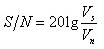
2. Time domain analysis Time domain analysis is usually to input a certain test signal into the audio device to be tested, and observe the time domain waveform of the output signal of the device to assess the relevant performance of the device. The most commonly used time-domain analysis test signals are sinusoidal signals, square wave signals, step signals, and single-tone mutation signals. For example, inputting a sinusoidal signal into the device and observing the time domain waveform distortion of the output signal is a time domain analysis method.
Square wave analysis has good abruptness and periodicity. By observing the output signal waveform of the square wave signal of the device, the performance of the device can be well detected. Therefore, the square wave signal has become the most commonly used time domain analysis signal. FIG. 1 is a detailed description of the response signal of the square wave of the audio device within half a period (rising edge). There are several main parameters to describe the square wave response, such as rise time, peak oscillation, overshoot and inclination.
The sinusoidal signal suddenly rises in peak value at a certain moment, forming a sudden change, which is a single-tone sudden change signal. Because the energy of the single-tone mutation signal is concentrated in a narrow frequency range, the single-tone mutation signal is commonly used to detect the response of the audio equipment at a specific frequency. The main purpose of the single-tone mutation signal is to quickly determine the damping characteristics of certain audio equipment, such as speakers. 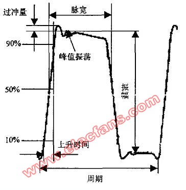
3. Frequency domain analysis Frequency domain analysis is an important content of audio analysis. The main basis of frequency domain analysis is the frequency response characteristic curve. The aforementioned sinusoidal detection, pulse detection and maximum length sequence signal detection can all obtain the frequency response of the device. The frequency response curve reflects the distribution of the frequency response of the audio device in the entire audio range. Generally speaking, the frequency component at the peak of the curve has large sound pressure and strong sound pressure during playback; the frequency component at the bottom of the curve has low sound pressure and weak sound. If the peaks and valleys fluctuate too much, it will cause more serious frequency distortion.
4. Time-frequency analysis Time-frequency characteristics describe the changes in the frequency domain characteristics of audio equipment over time on the time axis. The time-frequency characteristic not only describes the response state of the audio device during the frequency change, but also describes the response state of the audio device during the time change, that is, comprehensively describes the response characteristics of the audio device from a three-dimensional perspective. For playback equipment, subjective listening comments, such as whether the bass is clean, the background is clear, the level is clear, the depth of the sound field, etc. are closely related to the time-frequency characteristics of the audio equipment. The time-frequency characteristics of audio equipment is an important aspect of objectively evaluating the performance of audio equipment.
5. Distortion analysis The distortion of audio equipment includes harmonic distortion, intermodulation distortion, phase distortion and transient distortion. The most important thing in audio measurement is harmonic distortion. Harmonic distortion is simply the extra harmonic components that are generated after the sound signal is replayed by the audio equipment. From the perspective of the listener, the sounds emitted by different sounding objects are composed of different fundamental waves and harmonics, and the listener can distinguish the sounding objects according to the characteristics of the sound. If the power amplifier amplifies the tones (the tones are composed of fundamental waves and harmonics) emitted by a certain musical instrument, and after playing through the speaker, the waveform shape, amplitude and phase of the fundamental wave and each harmonic can be distortion-free If it is reproduced, it can be regarded as high-quality playback; otherwise, the sound emitted by the speaker sounds irritable and awkward, and the harmonic distortion has become unbearable, even making it impossible to distinguish the type of sounding instrument. Therefore, harmonic distortion is an important performance index of audio equipment.
There are two methods for measuring harmonic distortion. One is to input the device under test with a sinusoidal signal, and then analyze the frequency components of the response signal of the device to obtain harmonic distortion. Another simpler measurement method is to first use a band stop filter to filter out the fundamental frequency component of the response signal, and then directly measure the voltage of the remaining signal, and compare it with the original response signal to obtain harmonic distortion. Obviously, the harmonic distortion obtained by the second method is THD + N. Since the total voltage value of the signal is used instead of the voltage value of the fundamental frequency component, the resulting harmonic distortion is smaller than the actual value, and the actual harmonic distortion is more The larger, the greater the error.
In actual audio measurement, usually select several frequency points within a certain frequency range, measure the harmonic distortion of each point separately, and then connect each harmonic distortion value to the horizontal axis to form a curve, called harmonic Wave distortion curve. Figure 2 is a graph of the total harmonic distortion and 2nd, 3rd and 4th order harmonic distortion of a power amplifier in the range of 100-1OKHz. 
Audio parameter measurement and analysis Audio measurement generally includes basic parameters such as signal voltage, frequency, signal-to-noise ratio, and harmonic distortion. Most audio parameters can be composed of these basic parameters. Audio analysis can be divided into time domain analysis, frequency domain analysis, time frequency analysis and other categories. Because the harmonic distortion of the signal is more important for audio measurement, it is separately classified as distortion analysis. The following introduces various audio parameter measurement and audio analysis.