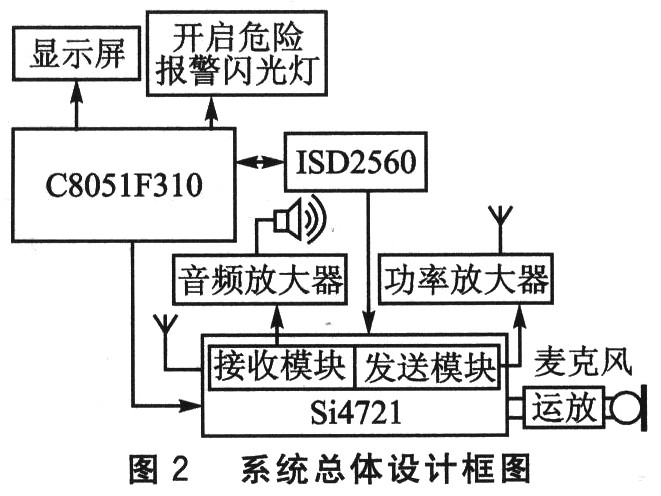
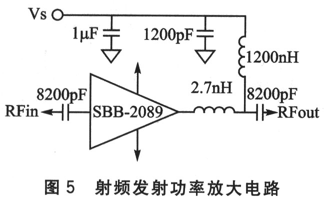
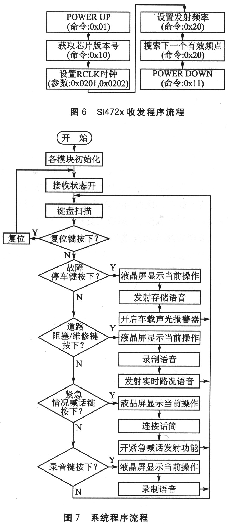
This system is mainly designed for the Si4721 series of chips launched by Silicon Lab. It can be modified slightly for other series of products. The design ideas are basically the same and the pins are compatible. 1 Si4721 single chip RF transceiver introduction Si472x functional block diagram is shown as in Fig. 1. The Si472x series mainly includes Si4720 and Si4721, both of which are in 20-pin QFN package, support FM signal 76 MHz ~ 108 MHz full band transceiver, and can automatically search the entire frequency band and frequency self-locking, operating voltage 2.7 ~ 5.5 V are both Be applicable. Its design is compatible with Si473x AM / FM broadcast receivers, Si470x FM broadcast receivers, and Si471x FM transmitter solutions. Because of this compatibility, a single PCB design can seamlessly support all of these products. When communicating with the microcontroller, 2-Wire, 3-Wire, and SPI interface methods compatible with I2C can be used. The main difference between Si4721 and Si4720 is that there is RDS / RBDS processor inside Si4721, which is a single-chip FM radio transceiver supporting European Broadcast Data System (RDS) and American Radio Broadcast Data System (RBDS). Si472x series chips are integrated with full-featured ADC and DAC components. External audio signals can be directly input into the chip for transmission. At the same time, the received audio signal can be driven by the speaker after being added to the amplifier. The new single-chip FM radio transceiver Si472x takes full advantage of unique RF expertise and achieves another innovation in integration and performance. It supports customers to further improve consumers' listening experience while simplifying system design and reducing product costs. The Si472x supports analog and digital audio interfaces and provides features such as recording FM radio as ringtones. Because no extra data converters are used, this digital audio interface can also reduce system power consumption and extend battery life. In addition, the Si472x FM transceiver is optimized for portable applications, with the ability to receive FM broadcast signals and the ability to create wireless audio connections from the device to any FM receiver. It is also a series of chips that support the integration of FM broadcast transceiver and can support miniaturized antennas. Due to the use of miniaturized antennas, Si472x series chips can be easily installed in many portable equipment PCB boards, including Bluetooth-enabled devices. Because it occupies very little PCB space, it can save many inconveniences caused by external antennas. 2 Working principle of road traffic condition prompting device The device mainly includes a core microcontroller, a single-chip FM transceiver, a voice circuit that can store and record multiple voice messages in real time, a power amplifier circuit and an audio amplifier circuit. The overall design block diagram of the system is shown in Figure 2. The system uses C8051F310 of Silicon Labs as the control core. The single-chip FM transceiver is implemented with a large-scale integrated chip Si4721, which can be programmed to work in receive or transmit mode, respectively. The voice module uses the integrated recording and playback chip ISD2560, which can record and store voice prompt information for various traffic conditions (such as license plate number, vehicle failure parking, road congestion or maintenance, etc.); at the same time, it can switch the recording microphone to directly speak out (such as vehicles There is a danger of explosion in fire, and people are trapped and cannot come out after a car accident). The device integrates receiving and sending. The default state is receiving, which can receive voice prompts or alarm signals from vehicles around 150 m away, and play them through the speaker in a loop so that the driver can make corresponding adjustments. When the vehicle breaks down due to a fault, or encounters rainy and foggy weather with low visibility, the single-chip computer is used to select the voice signal address stored in the voice chip in advance, and the voice content stored therein is recalled (for example: "the vehicle with the license plate number xxxxxxx sideways due to a fault" When parking, please drive carefully when you come behind! "), And then press the send button to send to the surrounding vehicles, and automatically turn on the hazard warning flasher in the car, in many ways to remind the rear to drive carefully. In case of road congestion and road maintenance, press the corresponding button to open the real-time input function of the voice module, and enter the corresponding information such as the name of the blocked road or the name of the repaired road (for example: "Some road section is now at the peak of the car race, please detour each vehicle Line "), press the send button, you can send the signal to the surrounding vehicles, so that other vehicles make timely choices. In the event of a vehicle accident, such as being trapped in a car or other emergencies, you can turn on the real-time shouting function, make a shouting directly through the microphone input circuit, and then transmit it through the transceiver module, and automatically turn on the hazard warning flasher in the car. 3 System hardware design 3.1 Transceiver hardware design The single-chip FM transceiver uses Si4721 chip, and the interface circuit is shown in Figure 3. The working frequency of the chip is provided by an external 32.768 kHz crystal oscillator, which is connected to the RCLK and DCLK pins respectively. 3. 2 microcontroller hardware design The system is controlled by single chip microcomputer C8051F310. The C8051F31x device is a fully integrated mixed-signal system-on-chip MCU chip that can realize all the functions of the 51 series single-chip microcomputer with fast speed and good performance. The purpose of choosing this powerful single-chip microcomputer is to lay the foundation for the subsequent development of the entire system, which is convenient for the subsequent upgrade and expansion of system functions. C8051F310 uses Silicon Labs' patented CIP-51 microcontroller core, with 29 I / O pins (3 8-bit ports and 1 5-bit port). The working conditions of the port are similar to the standard 8051, but there are some improvements . Each port pin can be configured as an analog input or digital I / O. A digital crossbar switch allows internal digital system resources to be mapped to port I / O pins. The on-chip counter / timer, serial bus, hardware interrupt, comparator output, and other digital signals inside the microcontroller can be configured to appear on the port I / O pins by setting the crossbar control register. This feature allows users to choose the combination of general-purpose port I / O and the required digital resources according to their specific application. The on-chip Silicon Labs second-line (C2) development interface allows non-intrusive (without occupying on-chip resources), full speed, and in-system debugging using the product MCU installed on the final application system. CIP-51 adopts pipeline structure, compared with the standard 8051 structure, the instruction execution speed is greatly improved. In a standard 8051, all instructions except MUL and DIV require 12 or 24 system clock cycles, and the maximum system clock frequency is 12 to 24 MHz. For the CIP-51 core, 70% of the instructions have an execution time of 1 or 2 system clock cycles, and only 4 instructions have an execution time greater than 4 system clock cycles. There are 111 instructions in CIP-51. When CIP-51 works at the maximum system clock frequency of 25 MHz, its peak speed reaches 25MIPS. 3.3 Hardware design of voice recording and playback circuit The voice circuit adopts the ISD2560 voice chip and controls its function pins CE, PD and P / R through the single chip microcomputer to realize the recording and processing of the audio signal collected by the microphone, and then output the signal to the Si4721 transceiver. Simultaneous access to the address line can store multiple recordings. Figure 4 is the principle of the voice circuit. The single-chip voice recording and playback integrated circuit ISD2560 can realize multi-functional voice recording and playback of multi-segment information processing. The maximum number of voice signal segments that can be stored is 600, and the recording time for each segment is 60 s. The chip adopts multi-level direct analog storage patent technology, eliminating the A / D and D / A converters. Each sampled value is directly stored in a single EEPROM unit on-chip, so it can reproduce voice, music, tones and effect sounds very realistically and naturally, avoiding the quantization noise and "metallic sound" caused by quantization and compression in general solid recording circuits . ISD2560 is highly integrated, including preamplifier, internal clock, timer, sampling clock, filter, automatic gain control, logic control, analog transceiver, decoder and 480 KB EPROM. 3.4 Hardware design of RF power amplifier circuit The RF power amplifier uses the power amplifier chip SBB-2089 from 50 to 850 MHz. In fact, the power gain can reach 20 dB, and the current transmission and reception distance can reach about 150 m. It is more suitable for traffic condition reminders. Without the permission of the committee, the receiving distance can be further expanded. The power amplifier circuit is shown in Figure 5. 4 System software flow Since the system is in the receiving state by default, only POWER UP is needed in the receiving program, and the corresponding command is 0x01; if you need to switch to the transmitting state, you must first switch to the POWER DOWN state, and then restart POWERUP. The Si472x transceiver program flow is shown in Figure 6, and the system program flow is shown in Figure 7. 5.1 Test environment Two sets of devices were used during the test, powered by 12 V nickel-manganese batteries. One set is for transmission and the other is for reception. The test distance is more than 150 m on the relatively empty tree-lined campus, the voice is clear, and the transmission distance is adjustable (if the committee does not allow it, it can be done further). In actual use, it can be powered by 12 V output from the car cigarette lighter. 5.2 Performance testing and evaluation After testing, the entire system has complete functions, and various performances such as transmission distance and voice quality meet the design requirements. The following is a detailed test situation: â‘ It can accurately receive the warning signals of vehicles over 150 m around; Conclusion This technology can be used for other purposes, such as walkie-talkies, doorbells and remote controllers, as long as it is modified and processed in addition to road traffic status prompts. This technology has a wide range of applications and has not yet reflected all its functions in this product. Our future development direction strives to improve this product.
The Foxboro® Programmable Automation Controller (PAC) System is a high-performance automation controller
and I/O subsystem integrated with easy-to-use Wonderware ® software. Foxboro PAC hardware marries high
performance, reliability and high I/O density with cost-effective redundancy options. The process modules and
I/O system form the basis of a complete distributed control and recording environment capable of continuous
analog, logic and sequential control combined with secure data recording at point of measurement; all
designed to maximize return on investment (ROI). Because it is engineered with some of the most advanced,
yet proven technologies available, the Foxboro PAC system is very powerful, yet so simple to use.
FOXBORO Cards: I / A Series system, FBM (input / output modules) sequential control, ladder logic control, accident recall processing, digital-to-analog conversion, input / output signal processing, data communication and processing.
Foxboro Cards,Foxboro Dcs Card,Foxboro Dcs Card Module,Foxboro Fbm202 Interface Module Xiamen The Anaswers Trade Co,.LTD , https://www.answersplc.com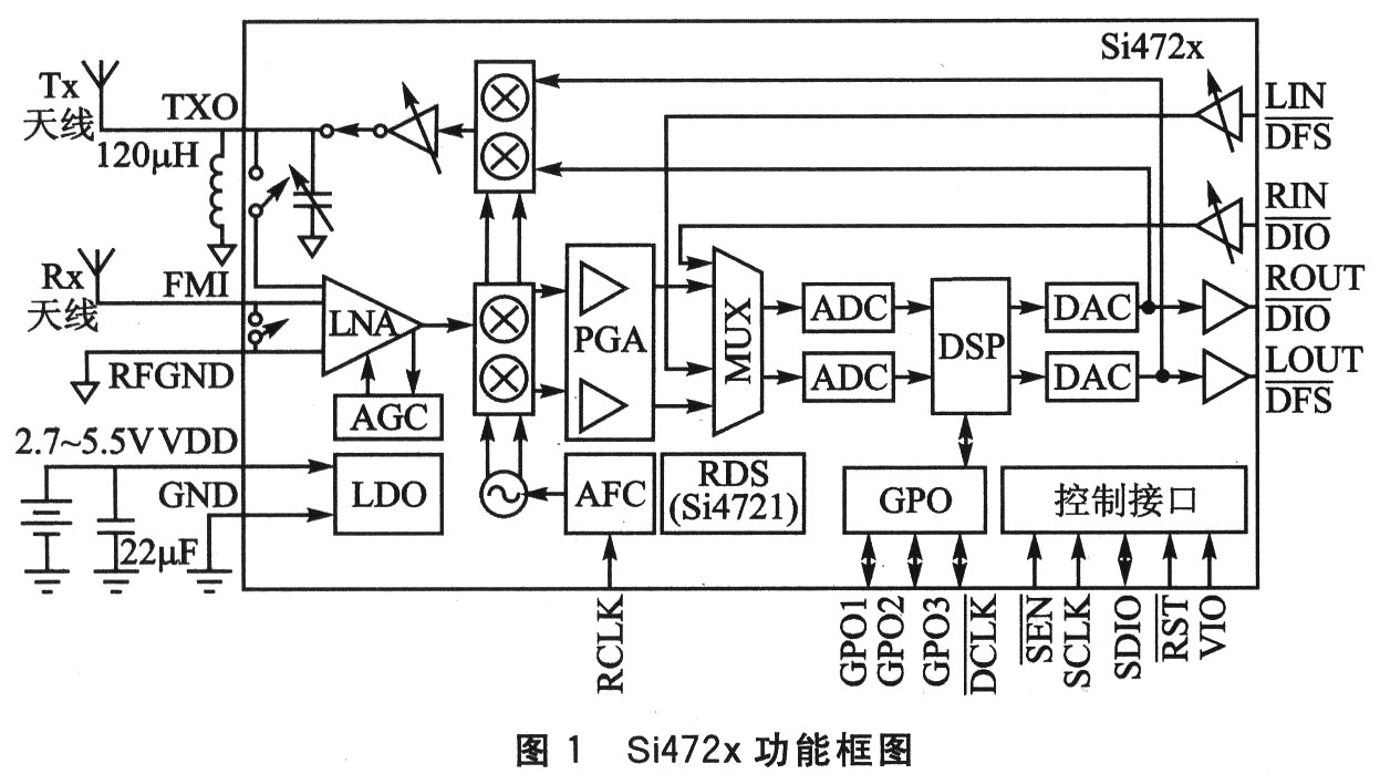
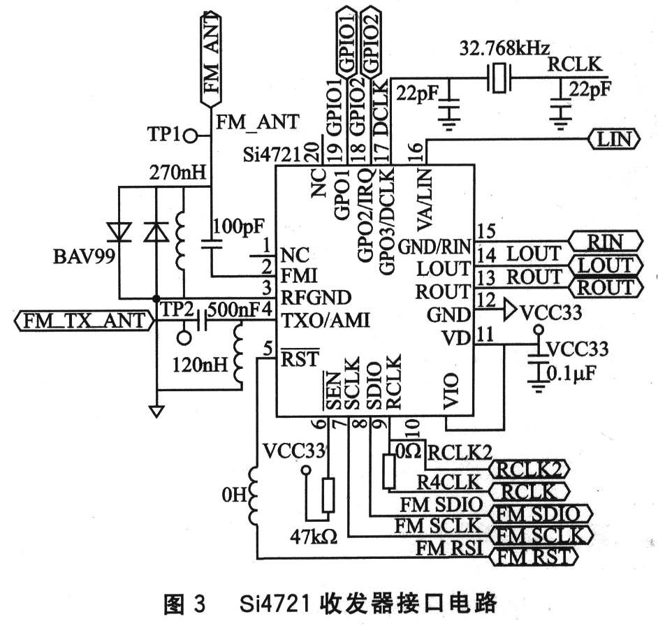 The Si4721 communicates with the microcontroller through the I2-C bus compatible 2-Wire operating mode. The single chip computer controls the Si4721 to work in the transmitting mode or the receiving mode through instructions. The voice signal output from the voice circuit is input to the Si4721, and then is transmitted through the Si4721 internal radio frequency circuit and antenna. The single chip microcomputer makes Si4721 work in the receiving mode by sending the receiving mode command. Set the relevant frequency band, and the signal received from the antenna is finally output from the speaker through the Si4721.
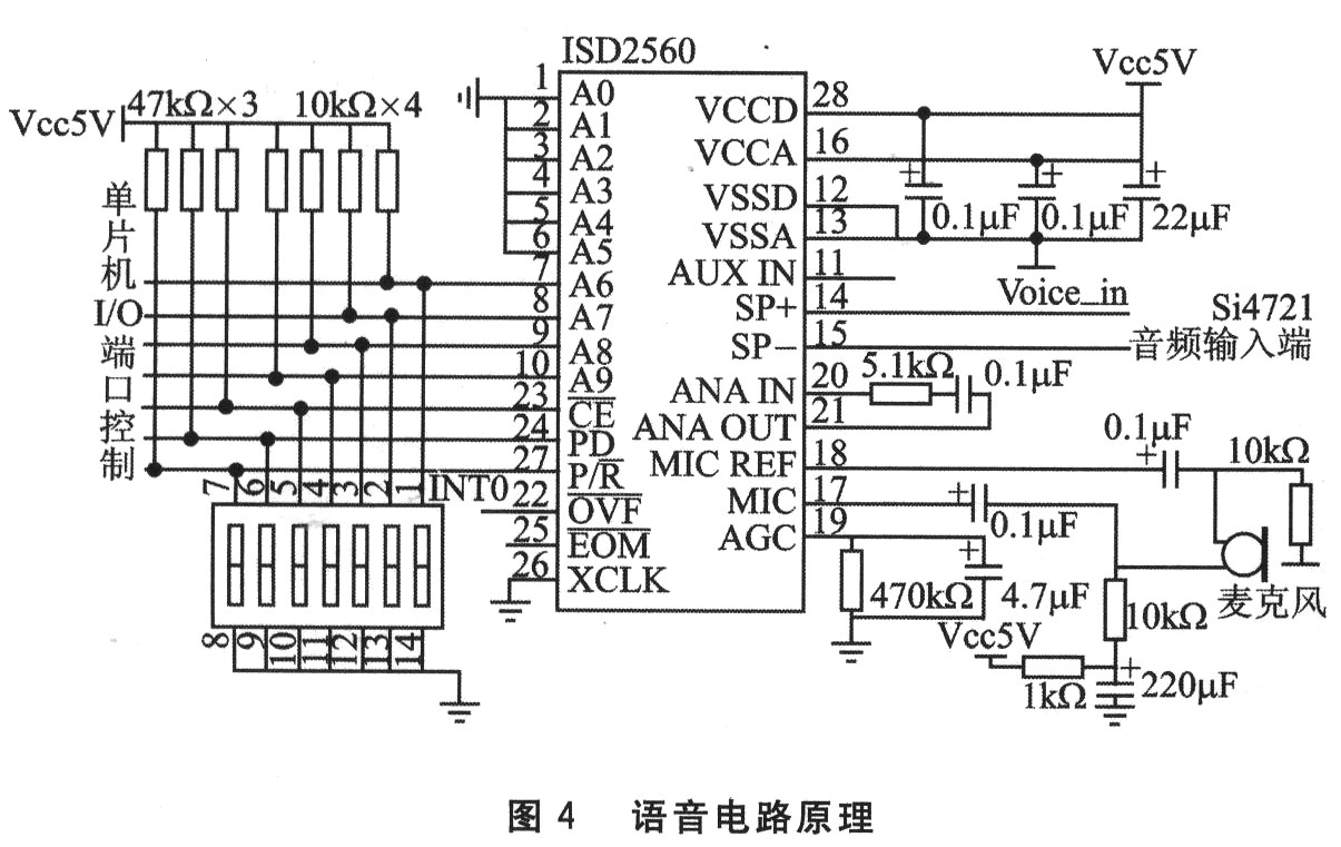
 5 System performance testing, evaluation and outlook
â‘¡ The received voice signal is clear and sweet;
â‘¢The name of blocked road or maintenance road can be entered in real time, and then sent out;
â‘£ The key delay detection confirms the sending function, effectively avoids the wrong sending;
⑤ Can realize multi-segment voice recording and playback management;
â‘¥ In emergency situations, you can speak directly to the outside world in real time;
⑦Automatically turn on the hazard warning flashlight in the car as required;
⑧Convenient interactive interface, LCD display operation tips, make the operation more convenient.
The currently used transmitter power amplifier is a low-power amplifier. For example, if the power amplifier is increased, the transmission distance of the transmitter can reach 500 m or more.

The traffic condition prompting device adopts FM transceiver technology, which can send reminder signals to surrounding vehicles in the case of road traffic accidents, road blockages or rain and fog weather with low visibility, and automatically turn on the hazard warning flasher in the car to remind the rear of the car At the same time, at the peak of the easy racing road, the road conditions can be conveyed to the surrounding vehicles in a timely manner. The device has a simple structure and low cost, and is convenient for installation on each car.