Design and manufacture of self-made car battery monitor 1. Function The car battery monitoring circuit is designed to solve the problem of being stuck on the road due to the failure of the battery. It can not only conveniently monitor the voltage of the car battery, but also monitor the working condition of the car charging circuit. The car battery monitoring circuit is also designed for electronics enthusiasts. By making this small circuit, not only can you meet your own needs, but you can also learn some circuit knowledge from the production process. 2. Design process Figure 1 is a light-emitting diode circuit. In general, a light-emitting diode in the circuit must be connected with a current-limiting resistor. The resistance value of the resistor is determined according to the operating current of the light-emitting diode. Here, VD1 selects the red Φ3 light-emitting diode and the resistance value of the resistor R1 is 1kΩ, so that the operating current of the light-emitting diode is about 1-10mA when the input voltage changes from 3-12V. 3. Production process The resistor used in the circuit is 1 / 8W, the transistor model is 9014 and other NPN type transistors, and the red and green light-emitting diodes are Φ3 highlight tubes. Zener diodes have stricter requirements and no suitable ones can be found. Two Zener diodes or silicon diodes in series can be used to meet the requirements. The production process is as follows: 4. Installation and use When using this circuit, simply connect it to the plug of the car cigarette lighter, and then directly plug it into the socket of the car cigarette lighter to monitor the car battery. Note that the head of the car cigarette lighter is the positive pole of the 12V circuit. I installed this circuit in the casing of an abandoned mobile phone charger, as shown in Figure 6. According to the shape of the charger, the circuit board installation diagram is given. As shown in Figure 7, the size is 30mm × 35mm. In the figure, several positions are reserved at the voltage regulator diode, and several diodes can be connected in series. 144 Port Fiber Patch Panel is not only does it provide physical security for sensitive network connections, it also promotes better organization.144 Fiber Patch Panel can suit for FC Adapter , ST Adapter , SC Adapter , LC Adapter etc,Suitable for ribbon and bunchy fiber cable.144 port fiber optic patch panel Components have Cover, inner components, fiber connecting protector Inner components.And inner components have Bracket,Fiber Optic Splice Tray,Fixing Device .The 144 Fiber Patch Panel Environmental temperature is -25 - 55°C. 144 Port Fiber Patch Panel 144 Port Fiber Patch Panel,144 Fiber Patch Panel,Fiber Optic Patch Panel 144 Port Foclink Co., Ltd , https://www.scfiberpigtail.com
Figure 2 adds a green Φ3 LED VD2, and a 10V Zener diode VD3 is connected in series in front of it, so that the green LED VD2 will only light up when the input voltage exceeds 12V. Resistor R2 is also a current limiting resistor. It is only because the Zener diode VD3 can have a voltage drop of 10V, so the resistance of the resistor R2 is only 100Ω. 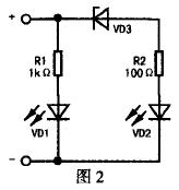
In order to make the battery voltage exceed 12V, only the green light-emitting diode VD2 is bright, and the red light-emitting diode VD1 is not bright, the circuit is provided with a transistor VT1 and resistor R3, see Figure 3. In this way, when the battery voltage exceeds 12V, the resistor R3 turns on the transistor VT1, and the red LED VD1 cannot obtain the proper working voltage at both ends (generally about 1.8 to 2V), so the red LED VD1 is not bright. 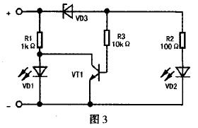
If the input voltage continues to rise, when it exceeds 13.5V, it indicates that the car generator is working properly and is charging the battery. In order to indicate this state without increasing the number of light-emitting diodes, the circuit is provided with a transistor VT2 and a trimming resistor RP. When the voltage exceeds 13.5v, the transistor VT2 is turned on, forcing the transistor VT1 to fail to turn on and to be turned off. In this way, both the red and green LEDs are on. Indicates that the car is charging. The complete electrical schematic is shown in Figure 4. 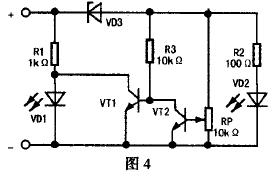
Step 1: Install red LED VD1 and resistor R1. Then install Zener diode VD3, green LED VD2 and resistor R2. Then use an adjustable DC stabilized power supply for debugging, requiring the green LED VD3 to be normal at 12V. If the voltage stabilizing value of the voltage stabilizing diode VD3 is slightly lower, then the green light-emitting diode will light up when the voltage does not rise to 12V, then you can find one or two diodes connected in series in the circuit. You can also use two zener diodes in series to form a 10V zener diode, as shown in Figure 5. 
Step 2: Install the transistor VT1 and resistor R3, and then turn on the 12V power supply, then the red LED VD1 should go out.
Step 3: Install triode VT2 and trimming resistor RP, connect it with DC regulated power supply for debugging, make the voltage rise from 12V to 13.5V, carefully adjust trimming resistor RP, make the trimming resistor RP midpoint voltage gradually from low Elevated, both green and red light-emitting diodes are on at 13.5V. At this point the circuit adjustment is complete. 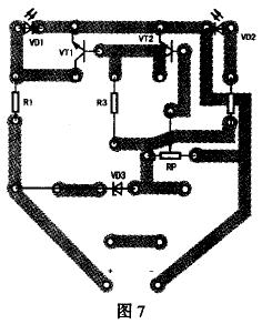
If the red light-emitting diode is on during use, the battery voltage is less than 12V. If the green LED is on, the battery voltage is normal. Start the car engine, both green and red light-emitting diodes are on, indicating that the charging circuit is normal.