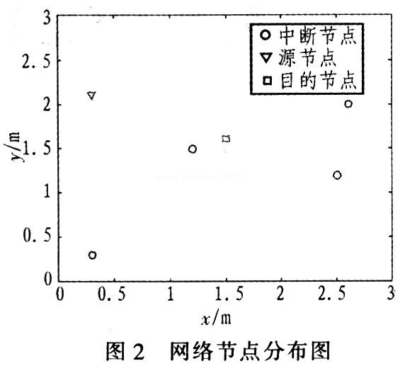
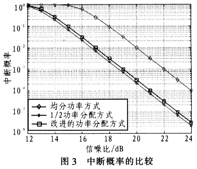
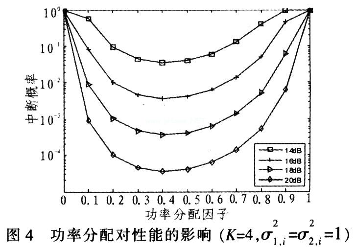
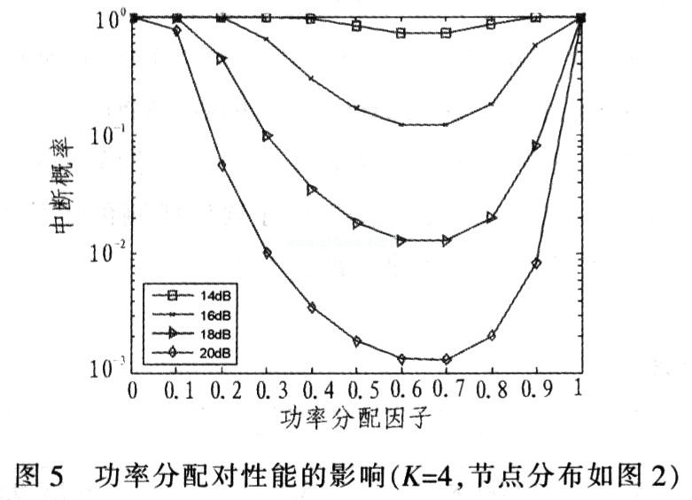
Optimized power distribution scheme for AF collaborative diversity 1 Introduction Cooperative communication technology refers to the use of multiple antennas of different users to form a virtual antenna array, thereby obtaining performance gains similar to MIMO systems. To increase system capacity through user collaboration, there are AF (Amplify and Forward) and DF (Decoded and Forward) collaboration methods. Diversity brought by collaboration is called collaborative diversity. AF means that the relay does not demodulate and decode the received signal, but directly amplifies and forwards it after analog processing. DF means that the relay first needs to demodulate, decode (if coded) and judge the received signal, and then encode and modulate the judged data before forwarding. In the AF mode, multiple diversity can be obtained. The multiple of the diversity is equal to the number of users participating in the collaboration. The AlamouTI space-time code is formed by using the antennas of other users, which is called space-time code coordination. Combining collaboration with channel coding is called Coded CooperaTIon. Its essence is to divide the codeword into two parts: data bits and parity bits to coordinate the redundancy parity bits. Cooperative diversity is only applicable to slow fading channels. For fast fading channels, cooperative diversity has little gain. 2 System model Figure 1 is a multi-user collaborative diversity communication model. Among them, h1.i is the channel from Sender (denoted as S) to Relay (denoted as R) i, and z1, i is noise. Similarly, h2, i is the channel from Re-lay i to DesTInation, and z2, i is the corresponding noise. Make the following assumptions: there are K relays, one transmitter and one relay, and the receivers are all single antennas. All terminals are half-duplex, that is, they cannot send and receive signals simultaneously. In the first time slot, the transmitter S transmits the signal x, relays Ri (i ∈ 1, 2, ... K) and the receiver D receives the signal. In the second time slot, the relay Ri amplifies and forwards the signal, and S does not send a new signal. h0 is the fading channel from S to D, h1, i is the channel from S to Ri, and h2, i is the channel from Ri to D. z0, z1, z2, i are additive white Gaussian noise of the corresponding channel. h0, h1, i, h2, i are complex Gaussian random variables with mean zero and independent, and their variances are 3 Simulation verification Simulation in quasi-static Rayleigh flat fading channel. Take R = 1 bps / Hz, σ2 = 1. Calculate the power distribution effect numerically. In order to make the result general, the network nodes are randomly generated in the 3 × 3 xOy rectangular coordinate system as shown in Figure 2, and the source node has 4 relay nodes. According to the simulation, it is assumed that any source node to the relay node, and the channel fading coefficients between the relay node and the destination node are respectively subject to the mean value. The interruption probability in Figure 3 is the numerical result calculated according to formula (3). For comparison. Here are also given the interruption probability performance curves of 2 traditional algorithms. Traditional algorithm 1 distributes the power equally between the source and all relay nodes, while traditional algorithm 2 distributes half of the power to the source. All relays allocate half the power on average. As can be seen from Figure 3, at an interruption probability of 10-3dB, this algorithm brings about 3 dB and 0.5 dB gain over traditional algorithm 1 and algorithm 2 respectively. Figures 4 and 5 simulate system outage probabilities at different power allocation factors. Figure 4 shows the simulation results when there are 4 relay nodes in the system and the distances between the source and the relay, and between the relay and the receiver are equal. At this time, the channel average gain is taken, σ1, i2 = σ2, i2 = 1. FIG. 5 is a simulation for the node distribution of FIG. 2. You can see from Figure 4. The power distribution factor is the best power distribution scheme at about 0.41, and δ≈0.41 can be obtained from equation (7). It can be seen from Fig. 5 that the power distribution factor is the best power distribution scheme at about 0.7, and δ≈0.704 can be obtained from equation (7). 4 Conclusions An improved power allocation strategy for relay nodes is proposed for multi-relay amplification and forwarding cooperative communication networks. Under the condition of a certain power, the optimal power allocation based on the cooperative diversity of the AF mode is analyzed, and all potential relay nodes are optimally allocated according to the average channel status information, thereby improving the utilization of system resources. Theoretical and simulation analysis shows that the scheme is superior to the two traditional algorithms. However, since the power distribution at the relay end involves all channels and noise in the entire transmission, whether it is S → D or R → D transmission, there is obviously more complexity.
APM Dc Source System is designed to meet customer`s high power/voltage/current command. User can quickly and easily operate the Dc Power Supply with its rotary knobs and buttons. Besides, free monitoring software for you to remote control the Adjustable Dc Power Supply.This series is applicable to multiple sectors such as electric, lighting and aviation sectors and it could be applied to enterprise's production test as well.
Some features as below:
600V Dc Source System,Dc Telecom System,Dc Source,600V Dc Power Source APM Technologies (Dongguan) Co., Ltd , https://www.apmpowersupply.com
For the AF mode, a method of power distribution at the relay end: the transmitting end uses half of the power, and all the relay ends use the other half of the power and the power is equally divided, but this method does not consider optimizing the receiving end or considering each channel power factor. The power is evenly distributed at the sending end and the relay end, and the maximum ratio combining MRC (Maximum RaTIo Combiner) is performed at the receiving end. Although the method is simple, the performance is not optimal. This paper proposes a power optimization allocation scheme aiming at reducing the outage probability of the system under the condition of large signal-to-noise ratio. 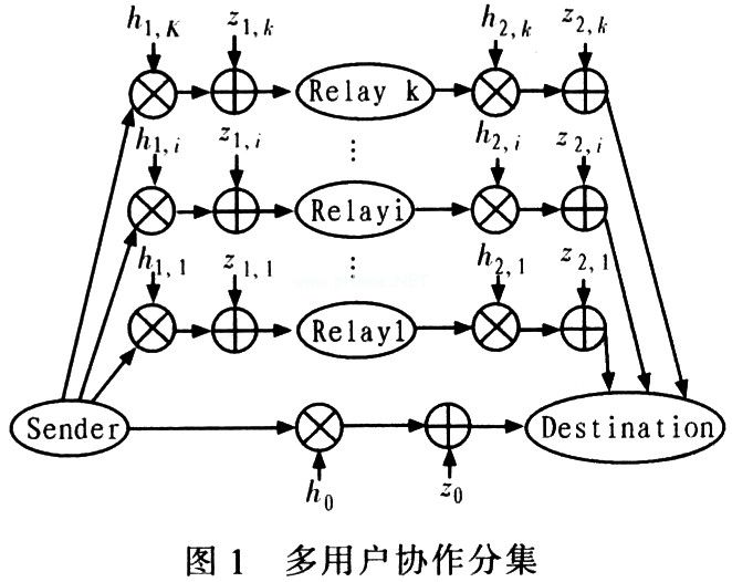
![]() It is independent of complex Gaussian random variables with mean zero and variance σ2.
It is independent of complex Gaussian random variables with mean zero and variance σ2.
All K relay nodes participate in cooperative communication, and the receiving end node processes the received signal using the maximum ratio and merge method. For the amplification and forwarding strategy, the instantaneous mutual information is: 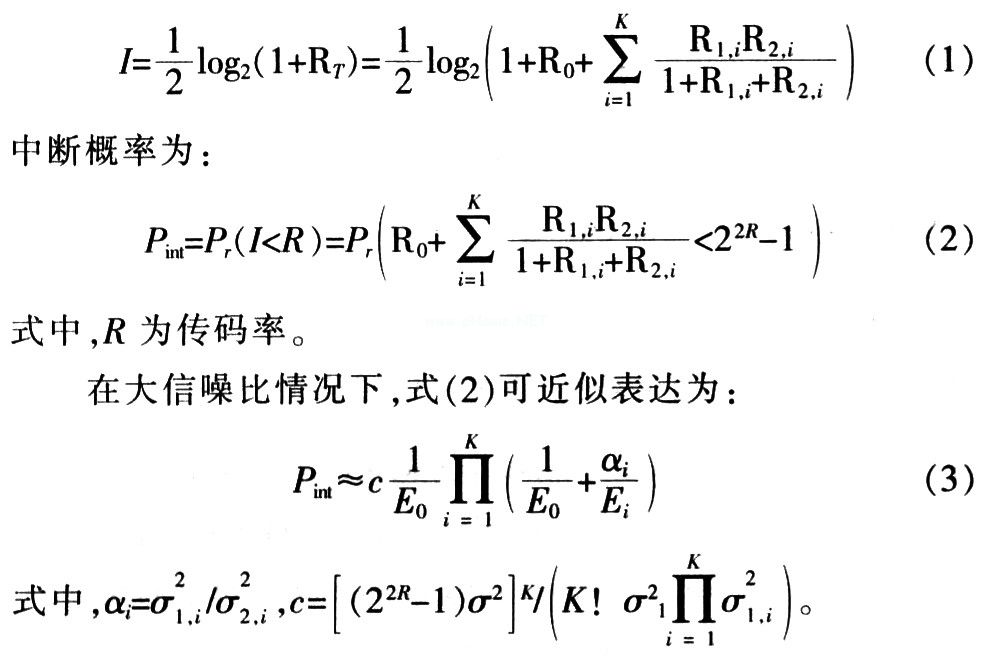
The total transmit power of the signal is ![]() To minimize the probability of interruption, according to the Lagrange multiplier method, let:
To minimize the probability of interruption, according to the Lagrange multiplier method, let: 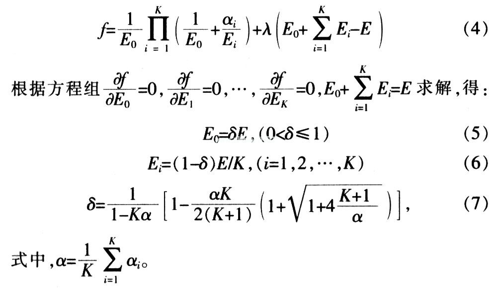
It can be seen that when α → 0, δ → 1, that is, when the ratio of the channel gain from the source to the relay and the relay to the receiving end is sufficiently small, power is allocated to the transmission from the source to the receiving end, ![]() It can be seen that when the ratio of the channel gain from the source to the relay and the relay to the receiving end is sufficiently large, the power is evenly distributed.
It can be seen that when the ratio of the channel gain from the source to the relay and the relay to the receiving end is sufficiently large, the power is evenly distributed. ![]() The Rayleigh distribution of, the relationship between the variance and the distance d0, d1, i, d2, i between the two nodes is: σ20 = cd
The Rayleigh distribution of, the relationship between the variance and the distance d0, d1, i, d2, i between the two nodes is: σ20 = cd ![]() Where c is a constant related to the propagation environment, and η is the path loss index, and its value is generally between 2 and 5. Without loss of generality, η = 4 and c = 1 in the simulation.
Where c is a constant related to the propagation environment, and η is the path loss index, and its value is generally between 2 and 5. Without loss of generality, η = 4 and c = 1 in the simulation.