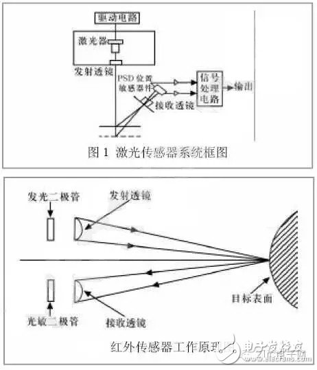
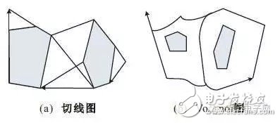
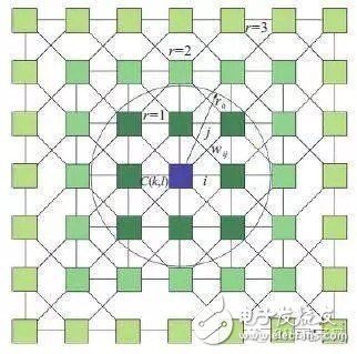
According to statistics from market research institutions, the market value of China's industrial robots reached US$1.3 billion in 2015, and will maintain a 20% annual compound growth (CAGR), reaching US$3.3 billion by 2020. In 2015, China’s industrial robot sales accounted for 13% of the world's total, and by 2020 it will reach 25%. The acquisition of Cook by the beautiful flower is probably also a good development momentum for industrial robots. Industrial robots belong to one kind of intelligent robots. Intelligent robots are developing rapidly. Let's take a look at the three key technologies used in intelligent robots. First, multi-sensor information fusion Multi-sensor information fusion technology is a hot research topic in recent years. It combines control theory, signal processing, artificial intelligence, probability and statistics to provide robots with tasks in a variety of complex, dynamic, uncertain and unknown environments. A technical solution. The key issues of data fusion are model design and fusion algorithms. Data fusion models mainly include functional models, structural models and mathematical models. The functional model starts from the fusion process, describes the main functions and databases involved in data fusion, and the interaction process between the components of the system during data fusion. The structural model starts from the composition of data fusion and describes the software and hardware of the data fusion system. Composition, related data flow, human-machine interface between system and external environment; mathematical model is data fusion algorithm and integrated logic, the algorithm mainly includes distribution detection, spatial fusion, attribute fusion, situation assessment and threat estimation algorithm, etc. The aspects are introduced separately. 1. Functional model of information fusion At present, many scholars have proposed the general functional model of information fusion system from different angles. The most authoritative is DFS (Data Integration Expert of C3I Technical Committee (TPC3) under the US Armed Forces Government-Laboratory Joint Committee (JDL). Group) proposed functional model. The model divides data fusion into three levels. Level 1 is single-source or multi-source processing, mainly digital processing, tracking correlation and correlation; level 2 is a collection of evaluation target estimates, and their relationship to each other to assess the whole situation; level 3 uses a system A priori set of targets to test the assessment. 2. Structural model of information fusion The structural model of data fusion has a number of different classification methods, one of which is classified according to the extent to which the sensor data has been processed before being sent to the fusion processing center. Under this classification standard, the fusion structure is divided into sensor-level data fusion, central-level data fusion and hybrid fusion, and the fusion structure can be classified according to the resolution of the data processing process. In this case, the fusion structure is a pixel level, feature level, and decision level fusion. 3. Mathematical model of multi-sensor information fusion The method of information fusion involves many aspects of theory and technology, such as signal processing, estimation theory, uncertainty theory, pattern recognition, optimization techniques, fuzzy mathematics and neural networks. Currently, these methods are broadly divided into two categories: random class methods and artificial intelligence methods. Second, navigation and positioning In the robot system, autonomous navigation is a core technology and a key and difficult problem in the field of robot research. There are four common navigation and positioning methods for autonomous mobile robots. 1, visual navigation and positioning In the visual navigation and positioning system, the current application at home and abroad is based on local vision, the navigation method of installing the vehicle camera in the robot. In this navigation mode, the control device and the sensing device are loaded on the robot body, and high-level decisions such as image recognition and path planning are all completed by the vehicle control computer. The visual navigation positioning system mainly includes: a camera (or CCD image sensor), a video signal digitizing device, a DSP-based fast signal processor, a computer and peripherals thereof. There are many robot systems that use CCD image sensors. The basic component is a row of silicon imaging elements. Photosensors and charge transfer devices are arranged on a substrate. The video signals of multiple pixels are time-sharing and sequential by the sequential transfer of charges. Take out the image, such as the image acquired by the area CCD sensor, the resolution can be from 32 & TImes; 32 to 1024 & TImes; 1024 pixels. The working principle of the visual navigation and positioning system is simply to optically process the environment around the robot. The camera first collects the image information, compresses the collected information, and then feeds it back to a neural network and statistical methods. The learning subsystem, and then the learning subsystem associates the acquired image information with the actual position of the robot to complete the autonomous navigation and positioning function of the robot. 2, light reflection navigation positioning A typical light reflection navigation positioning method mainly uses a laser or an infrared sensor to measure distance. Both laser and infrared use light reflection technology for navigation and positioning. The laser global positioning system generally consists of a laser rotating mechanism, a mirror, a photoelectric receiving device, and a data acquisition and transmission device. During operation, the laser is emitted outward through the rotating mirror mechanism. When scanning the cooperative road sign formed by the retroreflector, the reflected light is processed by the photoelectric receiving device as a detection signal, and the data acquisition program is started to read the code wheel data of the rotating mechanism ( The measured angle value of the target is transmitted to the host computer for communication through communication. According to the position of the known road sign and the detected information, the position and direction of the sensor under the landmark coordinate system can be calculated to achieve further navigation. The purpose of positioning. The figure is a block diagram of an LDSR laser sensor system. Laser ranging has the advantages of narrow beam, good parallelism, small scattering, high resolution in the ranging direction, but it is also greatly interfered by environmental factors. Therefore, how to denoise the collected signal when using laser ranging is also a Larger problems, and laser ranging also have blind spots, so it is difficult to achieve navigation by laser. In industrial applications, it is generally used in industrial areas where specific areas are detected, such as detecting pipeline cracks. . Infrared sensing technology is often used in multi-joint robotic obstacle avoidance systems to form a large-area robot "sensitive skin" that covers the surface of the robot arm and can detect various objects encountered during the operation of the robot arm. The typical infrared sensor works as shown. The sensor includes a solid state light emitting diode that emits infrared light and a solid state photodiode that acts as a receiver. The modulated signal is emitted by the infrared light-emitting tube, and the infrared photosensitive tube receives the infrared modulated signal reflected by the target object, and the elimination of the ambient infrared light interference is ensured by the signal modulation and the dedicated infrared filter. Let the output signal Vo represent the voltage output of the reflected light intensity, then Vo is a function of the distance from the probe to the workpiece: Vo=f(x,p) Where p is the reflection coefficient of the workpiece. p is related to the surface color and roughness of the target. X—the distance from the probe to the workpiece. When the workpiece is a similar target with the same p value, x and Vo correspond one-to-one. x can be obtained by interpolation of experimental data of proximity measurement of various targets. In this way, the position of the robot from the target object can be measured by the infrared sensor, and the mobile robot can be navigated and positioned by other information processing methods. Although infrared sensing positioning also has the advantages of high sensitivity, simple structure, low cost, etc., because of their high angular resolution and low range resolution, it is often used as a proximity sensor in mobile robots to detect adjacent or sudden motion. Obstacle, easy robotic emergency stop. 3, GPS global positioning system Nowadays, in the application of navigation and positioning technology of intelligent robots, pseudo-distance differential dynamic positioning method is generally used. The reference receiver and the dynamic receiver jointly observe 4 GPS satellites, and according to a certain algorithm, the robot can be obtained at a certain moment. Three-dimensional position coordinates. Differential dynamic positioning eliminates the star clock error. For users 1000km away from the base station, the star clock error and the tropospheric error can be eliminated, which can significantly improve the dynamic positioning accuracy. However, in mobile navigation, the positioning accuracy of the mobile GPS receiver is affected by the satellite signal condition and the road environment, and is also affected by many factors such as clock error, propagation error, receiver noise, etc. Therefore, the positioning accuracy is purely using GPS navigation. The problem is relatively low and the reliability is not high, so in the navigation application of the robot, the data of the magnetic compass, the optical code disc and the GPS are usually used for navigation. In addition, GPS navigation systems are not suitable for use in indoor or underwater robot navigation and for robotic systems where position accuracy is high. 4, ultrasonic navigation and positioning The working principle of ultrasonic navigation and positioning is similar to that of laser and infrared. Usually, the ultrasonic probe emits ultrasonic waves, and the ultrasonic waves encounter obstacles in the medium and return to the receiving device. By receiving the ultrasonic reflection signal emitted by itself, and calculating the propagation distance S according to the ultrasonic transmission and the echo receiving time difference and the propagation speed, the distance from the obstacle to the robot can be obtained, that is, there is a formula: S=Tv/2, T – the time difference between the transmission and reception of the ultrasonic wave; v—the wave velocity of the ultrasonic wave propagating in the medium. Of course, there are also a number of mobile robots used in the navigation and positioning of separate transmitting and receiving devices, a plurality of receiving devices are arranged in the environment map, and a transmitting probe is mounted on the mobile robot. In the navigation and positioning of mobile robots, because of the defects of the ultrasonic sensors themselves, such as: specular reflection, limited beam angle, etc., it is difficult to obtain sufficient information of the surrounding environment. Therefore, an ultrasonic sensing system composed of multiple sensors is usually established. The corresponding environment model transmits the information collected by the sensor to the control system of the mobile robot through serial communication. The control system then adopts a certain algorithm according to the collected signal and the established mathematical model to perform corresponding data processing to obtain the position environment of the robot. information. Ultrasonic sensors have long been widely used in the navigation and positioning of mobile robots because of their low cost, fast information acquisition rate and high range resolution. Moreover, it does not require complicated image matching technology when collecting environmental information, so the distance measurement is fast and the real-time performance is good. At the same time, ultrasonic sensors are also not susceptible to external environmental conditions such as weather conditions, ambient lighting and obstacle shadows, surface roughness. Ultrasonic navigation positioning has been widely applied to the sensing systems of various mobile robots. Third, path planning Path planning technology is an important branch of robotics research. The optimal path planning is based on one or some optimization criteria (such as the lowest working cost, the shortest walking route, the shortest walking time, etc.), and finds a path from the initial state to the target state in the robot workspace, which can avoid obstacles. Optimal path. The mobile robot path planning technology is roughly divided into the following four categories: template matching path planning technology, artificial potential field path planning technology, map construction path planning technology and artificial intelligence path planning technology. 1. Template matching path planning technology The template matching method compares the current state of the robot with the past experience, finds the closest state, and modifies the path in this state to obtain a new path, that is, firstly using the information used or generated by the path planning. A template library, any template in the library contains environmental information and path information for each planning. These templates can be obtained through specific indexes; then the current planning tasks and environment information are matched with the templates in the template library to find out An optimal matching template; then the template is modified, and as a final result, the template matching technology has better application effects in the case of environmental determination, such as the case-based autonomous underwater robot proposed by Vasudevan et al. AUV) path planning method, the template matching path planning method of cleaning robot proposed by Liu et al. In order to improve the adaptability of template matching path planning technology to environmental changes, some scholars have proposed a method of combining template matching with neural network learning, such as Ram et al. combine case-based online matching with enhanced learning It improves the adaptive performance of the robot in the template matching planning method, enables the robot to partially adapt to the changes of the environment, and the path planning method that combines the environmental template and the neural network learning by Arleo. 2. Artificial potential path planning technology The basic idea of ​​artificial potential path planning technology is to regard the movement of the robot in the environment as a movement of the robot in the virtual artificial force field. The obstacle generates a repulsive force to the robot, the target point generates gravity to the robot, and the resultant force of gravity and repulsive force acts as the control force of the robot, thereby controlling the robot to avoid the obstacle and reach the target position. The early artificial potential field path planning research is an artificial potential field in a static environment. The obstacles and targets are regarded as static and invariant. The robot only plans the motion path according to the specific location of obstacles and targets in the static environment. Regardless of their speed of movement. However, the environment in the real world is often dynamic, and obstacles and targets may be mobile. In order to solve the path planning problem of robots in dynamic environments, Fujimura et al. propose a relatively dynamic artificial potential field method to see the time. It is a one-dimensional parameter of the planning model, and the moving obstacle is still regarded as static in the extended model, so that the dynamic path planning can still be implemented by the static path planning method. The main problem with this method is that the trajectory of the robot is always known, but this is difficult to achieve in the real world. For this reason, Ko et al. introduce the velocity parameter of the obstacle into the construction of the repulsion potential function, and propose a dynamic environment. The path planning strategy is given, and the simulation results are given. However, the two assumptions of the method make it distance from the actual dynamic environment: (1) only consider the moving speed of the obstacle in the environment, and do not consider the moving speed of the robot. (2) It is considered that the relative speed between the obstacle and the robot is fixed, which is not a complete dynamic environment. For the dynamic path planning problem, the main obstacles related to robot obstacle avoidance are the relative position and relative speed between the robot and the obstacle, rather than the absolute position and speed. For this, Ge and so on will compare the relative position of the robot with the target. The relative velocity introduces the attractive potential function, and the relative position and relative velocity of the robot and the obstacle are introduced into the repulsive potential function. The robot path planning algorithm in dynamic environment is proposed, and the algorithm is applied to the path planning of the omnidirectional soccer mobile robot. Satisfactory simulation and experimental results. 3. Map construction path planning technology The map construction path planning technology divides the surrounding area of ​​the robot into different grid spaces (such as free space and restricted space) according to the obstacle information searched by the robot's own sensor, and calculates the obstacle possession of the grid space, and then based on A certain rule determines the optimal path, and the map construction is divided into a road sign method and a grid method, also called a unit decomposition method. The former is to construct a feasible path diagram of the robot consisting of marker points and connecting edges, such as visual line method, tangential method, Voronoi diagram method and probability map expansion method. The view method treats the robot as a point, and the vertices of the robot, the target point and the polygon obstacle are combined and connected, and the lines are not intersected with the obstacle, so that a picture is formed, which is called a view, due to any two The vertices of the line are visible. All the paths from the starting point along the straight line to the target point are the collision-free paths of the moving object. The path planning is to search for the shortest distance problem from the starting point to the target point through these visible lines; the tangential chart The method and the Voronoi diagram method are used to transform the viewable method. The tangential method is based on the polygonal obstacle model. The arbitrary shape obstacle is replaced by the approximate polygon, and the tangential map is constructed in the free space. Therefore, the robot from the starting point to the target point is Walking along a tangent, that is, the robot must walk almost close to the obstacle, the path is short, but if a position error occurs during the control, the possibility of collision of the mobile robot is high, and the Voronoi diagram consists of a series of straight and parabolic segments. The line is generated by the vertices of two obstacles or the edges of two obstacles, all on the straight line Must be equal to the apex of the obstacle or the edge of the obstacle. The parabolic segment is defined by the apex of an obstacle and the edge of an obstacle. The parabolic segment also requires the same distance from the apex of the obstacle and the edge of the obstacle, compared with the tangent method. In comparison, the Voronoi diagram will increase the path from the starting node to the target node. However, even with the position error, the mobile robot will not encounter obstacles and the safety is high. The following figure is tangent. Diagram and Voronoi diagram. Tangent graph method and Voronoi graph method The grid method is to decompose the space around the robot into interconnected and non-overlapping spatial units; a grid, which forms a connected graph, and searches for a slave starting grid based on the obstacle occupancy. The optimal path from the grid to the target grid without collision. Among them, according to different grid processing methods, it is divided into precise grid method and approximate grid method, the latter also called probability grid method. The precise grid method is to decompose the free space into a plurality of non-overlapping units. The combination of these units is exactly equal to the original free space. The following figure is a commonly used precise grid decomposition method—trapezoidal grid decomposition. Unlike the exact grid method, all grids of the approximate grid method are of a predetermined shape, usually rectangular, and the entire environment is divided into a plurality of larger rectangles, each of which is continuous, a typical method. It is a "quadruple tree" method. If a large rectangle contains obstacles or boundaries inside, it is divided into 4 small rectangles, which are divided into all slightly larger grids, and then formed in the final boundary of the division. The program is repeated between small grids until the limit of the solution is reached. The map construction method is straightforward. It is often integrated with other path planning methods, such as the map construction path planning algorithm of ART neural network proposed by Araujo, the map construction path planning of Kalman filter proposed by Najjaran, and the bio-inspired proposed by Yang et al. The cleaning robot integrated with the neural network and the map construction completely covers the path planning technology (CCPP) and the like. At present, map construction technology has attracted extensive attention in the field of robot research, and has become one of the research hotspots of mobile robot path planning. However, robot sensor information resources are limited, making grid map obstacle information difficult to calculate and process, and because the robot is dynamic It is difficult to ensure the real-time of path planning when the number of grids is large and the resolution is high. Therefore, the map construction method must balance the map grid resolution and path planning real-time. 4. Artificial intelligence path planning technology Artificial intelligence path planning technology applies modern artificial intelligence technology to the path planning of mobile robots, such as artificial neural networks, evolutionary computation, fuzzy logic and information fusion. Genetic algorithm is the earliest intelligent optimization algorithm applied to combinatorial optimization problem. The algorithm and its derivative algorithm have been applied in the field of robot path planning research. Based on the better solution of traveling quotient problem (TSP) by ant colony algorithm, many scholars further The ant colony optimization algorithm was introduced into the path planning research of underwater robots (UV). As an important part of artificial intelligence, neural network has received extensive attention in mobile robot path planning research. For example, Ghatee applied Hopfield neural network to path distance optimization; Zhu et al applied self-organizing SOM neural network to multi-task multi-robot. In the task assignment and path planning, in recent years, Canadian scholar Simon proposed a new biological heuristic dynamic neural network model, which associates the neural network neurons with the discrete coordinates of the two-dimensional planning space, by specifying obstacles and non-obstacles. For the difference between the input excitation and suppression of the neuron, the output of the relevant neuron is directly calculated, thereby determining the running direction of the robot. Since the neural network does not need to learn the training process, the path planning has good real-time performance, and at the same time, the rapid attenuation of the neural network itself is utilized. Characteristics, better solved the dead zone problem of robot path planning. The figure shows the structure of the biological heuristic neural network used for local path planning. The figure shows the sensory radius of the robot (at the neuron). Each neuron corresponds to the environmental position coordinates, and dynamically calculates the neighboring neuron output of the robot. The robot determines the next running target according to the output size of the neuron, thereby achieving safe path planning. Artificial intelligence technology is applied to mobile robot path planning, which enhances the "smart" characteristics of robots and overcomes the shortcomings of many traditional planning methods. However, this method also has shortcomings. The genetic optimization and ant colony algorithm path planning techniques are mainly for path planning. Some of the problems in the process, using evolutionary computation for optimization, and combined with other path planning methods, are less likely to complete path planning tasks alone. Information fusion technology is mainly applied to robot sensor signal processing, rather than direct path planning strategy. For neural network path planning, most neural network path planning has a learning process of planning knowledge, which is not only difficult to obtain learning samples, but also There is a problem of learning lag, which affects the real-time nature of neural network path planning. Although bio-inspired neural network path planning has better real-time performance, there are also artificial uncertainties in the setting of input excitation and suppression. Bio-inspired neural network path planning In addition, intelligent robots also use robot vision, intelligent control, human-machine interface technology and other technologies, Xiaobian will not repeat them, you can search for relevant information and share it. L2/L3 Managed Industrial Switches
The Layer 2 switch generally cannot control the transmission protocol, but can only control the data link, so the Layer 2 switch can only be addressed through the mac address, because the mac address acts on the data link layer. The three-layer switch can be controlled to the network layer, which means that the three-layer switch can be addressed by IP address. Now high-end switches can control up to seven layers, and can control the flow and bandwidth of the application layer protocol in the network.
The Layer 3 switch can be integrated with VLAN and routing functions. The three-layer forwarding engine uses hardware ASIC technology to realize IP forwarding.
Layer 2 switch has no routing function, and layer 3 has routing function Fiber Optic Switch,16 Port Managed Switch,L2 Management Network Switch,L3 Managed Industrial Switches Shenzhen Scodeno Technology Co.,Ltd , https://www.scodenonet.com
The communication between VLANs is routed
The two-layer switch works on the second layer (data link layer) of the OSI model, so it is called a two-layer switch. The development of the two-layer switching technology has been relatively mature. The two-layer switch is a data link layer device. It can identify the MAC address information in the data frame, forward it according to the MAC address, and record these MAC addresses and corresponding ports in its own internal An address table.