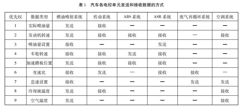
The data bus DB is used to transfer data information. The data bus is a bidirectional tri-state bus, ie it can transfer data from the CPU to other components such as memory or input/output interfaces, and it can also transfer data from other components to the CPU. The number of bits in the data bus is an important indicator of the microcomputer and is usually consistent with the word length of the microprocessor. For example, the Intel 8086 microprocessor has a 16-bit word length and its data bus width is also 16 bits. It should be pointed out that the meaning of data is broad, it can be real data, it can also be instruction code or status information, and sometimes even a control information. Therefore, in actual work, the data bus is not necessarily transmitted Only real data. The common data bus is ISA, EISA, VESA, PCI, and so on. 1. Bus bandwidth (Bus data transfer rate) The bus bandwidth refers to the amount of data transferred on the bus in a unit time, that is, the maximum steady-state data transmission rate for each MB transferred. The two factors that are closely related to the bus are the bus width and the operating frequency of the bus. The relationship between them is: Bus bandwidth = bus operating frequency * bus width/8 2, the bus width The bit width of the bus refers to the number of bits of binary data that can be transmitted by the bus at the same time, or the number of bits of the data bus, that is, the concepts of 32-bit, 64-bit, etc. bus widths. The wider the bit width of the bus, the greater the data transfer rate per second and the wider the bandwidth of the bus. 3, the bus operating frequency The operating clock frequency of the bus is in MHZ. The higher the operating frequency is, the faster the bus operates and the wider the bus bandwidth. (1) According to the type of wire, it is divided into the following three categories: 1 Single-line transmission, such as LIN bus. 2 two-wire transmission, such as CAN bus. At present, most new cars use the CAN Bus Bus System (CAN-BUS). 3 Wireless transmission, such as the Bluetooth bus ("Bluetooth"). (2) According to the data transmission rate, it is divided into the following three categories: Class A (low-speed network)—The data transmission bit rate is 1kbit/s to 10kbit/s, and is mainly applied to power windows, central control door locks, power seats, and lighting. Class B (medium-speed network) --- data transmission bit rate of 10kbit/s ~ 100kbit/s, mainly used in vehicle information center, fault diagnosis, instrument display, airbags and other systems. Class C (high-speed network)—The highest bit rate of data transmission is greater than 1 Mbit/s. It is mainly used in engine power control systems, automatic transmission control systems, drive slip control systems, and electronic suspension control systems. In the above three types of networks, Class C networks can simultaneously implement the functions of Class B networks and Class A networks. Class B networks support the functions of Class A networks. LIN: Multipoint synchronous "Asynchronous Receiver Transmitter", less than or equal to 19.2Kbps CAN: Widely use CSMA/CR bus system, less than or equal to 1Mbps FlexRay: Time-triggered TDMA bus and star system, less than or equal to 10Mbps MOST: Synchronous TDMA Ring, Supports 25, 50, 150 Mbps Sharing Ethernet (AVB): Switch-based full-duplex star system, 1000Mbps, LAN DataBus. It stipulates a method for sharing and exchanging data between homogeneous systems and heterogeneous systems in a large integrated application system. 1. Business entity data exchange: Each subsystem has a business entity layer in the architecture hierarchy, and the data exchange system establishes a layer that is transparent to all application systems at the business entity layer. Between subsystems, regardless of the specific technical solutions they implement, they can share and interact through the business entity layer. This also establishes a structure for continuous integration and business expansion between subsystems, thus achieving a scalable The complete integrated information system. 2. WebService data exchange: It is a kind of Web service standard. Web services provide solutions for sharing and exchanging data between heterogeneous systems, and can also be used for data sharing and exchange in product integration using a unified interface standard. 1. Data exchange at the business entity level, which is the most direct and efficient exchange scheme between homogeneous subsystem systems. Through the definition of data object interface layer between homogeneous subsystems, through the DTO for transmission, or directly in the database for data table connection or access, to achieve the sharing and exchange of data between homogeneous subsystems. For example, data sharing and exchange among various subsystems in the collection and management system, data sharing between business systems and data mining. 2. WebService data exchange, in the case of heterogeneous data between different subsystems, must use effective technical means to ensure heterogeneous data sharing and exchange. WebService is a Web-based standard service, which is not limited by the transmission protocol or hardware, and is not limited by the specific implementation technology of the subsystem. And now more advanced and complete application systems or products provide integrated interfaces based on WebService. This solves the data sharing and exchange among heterogeneous subsystems. WebService can also solve the data exchange between the network and the industrial system. This requires that the other interface unit also has the WebService service. 3 format file data exchange, it is with the external system file transfer, business on the internal system and external information exchange requirements, requires the provision of appropriate data sharing and exchange technology mechanisms. Such problems are usually solved using file system-based technical solutions such as file submission, file exchange, and so on. For example, there are real-time and non-real-time data exchanges between tax, library, and silver. This exchange-optimized solution uses files for exchange via Socket. This type of technology implementation generally uses the underlying technology. Data is transmitted between the control units on the data bus, and as the broadcast station transmits the programs, various signals are sent out. The receiver is not designated, and the control unit autonomously selects whether to receive the information (see Table 1). From the above table, it can be seen that several data such as engine speed, vehicle speed, and wheel speed are shared by various subsystems. Any control unit (ie, subsystem) on the CAN network can send information to the network at any time, regardless of master-slave, with point-to-point, point-to-multipoint, and global broadcast receiving and transmitting functions. Dongfeng Citroen Triumph Car adopts a full CAN data transmission system to replace the VAN/CAN coexisting structure. It consists of the following four subsystems, and the BSI (Intelligent Control Box) manages and coordinates the communication and power supply between each subsystem. To detect the car's CAN system, it should be connected to the CAN diagnostic connector (C001) using a dedicated Citroën PROXIA diagnostic tool to obtain CAN sub-system fault information. (1) Body CAN (CAN-CAR), speed 125kbit/s, fault tolerant. The CAN-CAR is connected to the electronic control unit of all safety devices in the vehicle. The so-called "fault-tolerant function" means that when a line in the network has an open circuit or a short-circuit fault, the network can still communicate normally, but it will remember a fault message. CAN-CAR's waveform standards are: peak value is 4V, low peak value is 0.8V (CAN-H and CAN-L are the same, but in the opposite direction). If the peak value of the detected waveform is very different or the waveform is confusing, it indicates that there is a fault in the network. (2) Comfort CAN (ie CAN-CONFORT), speed 125kbit/s, low speed, fault tolerance. CAN-CONFORT connects all the electronic control units of the electric facilities for the driver and passengers on the vehicle and the electronic control unit of the display device, forming a human-machine dialogue interface. The waveform standard of CAN-CONFORT is: Peak value is 4.5V, low peak is 0.8V. (3) Communication CAN (ie, CAN-I/S) at a rate of 500 kbit/s. CAN-I/S connects all electronic control units of the onboard power system, including the engine electronic control unit and the automatic transmission electronic control unit. The CAN-I/S cable is hinged by a CAN-H line and a CAN-L line. (4) Diagnostic CAN, rate 500 kbit/s. Diagnostic CAN can diagnose the electronic control unit in the remaining 3 subsystems, and can also download and encode the BSI software. Diagnostic CAN replaces the original K-line (but in the Dongfeng Citroën Triumph sedan, the ESP and suspension electronic control unit retains the traditional K-line for download functions), which greatly reduces the time required to diagnose and access the electronic control unit. .
3D printing on the pen machine is mainly used in 3 d printing pen, is made from a special custom Dc Gear Motor, mainly used in 3 d printing pen, pen 3 d printing machine has been updated three generations according to the requirements of product.
3D Printing Motor product introduction:
The 3D Printing Motor is based on the deceleration Motor, coupled with supporting gears and ball bearings.The role of the gear reducer is to provide lower speed and greater torque.At the same time, gear box different deceleration ratio can provide different speed and torque.It's mostly rolling.
Features: 3D Printing Motor, small size, large torque, low noise, durable, low energy consumption, customized power design, convenient installation and maintenance;
Simplify design and save space.
Features: usually used financial equipment,
office equipment, electronic locks, wireless charger, remote control toys, precision
instruments and meters, automobile industry, medical equipment, consumer
electronics, household appliances, electric glass doors and Windows, etc., wide
application range
Method
of use: the best stable in horizontal plane, installed on the 3D Printing Motor output
shaft parts, cannot use a hammer to knock, knock prone to press into the 3D Printing Motor drive, may cause damage to internal components, and cannot be used in the
case of blocked.
Operating temperature range:
3D Printing Motor should be used at a temperature of -10~60℃.
The figures stated in the catalog specifications are based on use at ordinary room temperature catalog specifications re based on use at ordinary room temperature (approximately20~25℃.
If a 3D Printing Motor is used outside the prescribed temperature range,the grease on the gearhead area will become unable to function normally and the motor will become unable to start.Depending on the temperature conditions ,it may be possible to deal with them by changing the grease of the motor's parts.Please feel free to consult with us about this.
Storage temperature range:
3D Printing Motor should be stored ta a temperature of -15~65℃.
In case of storage outside this range,the grease on the gearhead area will become unable to function normally and the motor will become unable to start.
Service life:
â—Use with a load that exceeds the rated torque
â—Frequent starting
â—Momentary reversals of turning direction
â—Impact loads
â—Long-term continuous operation
â—Forced turning using the output shaft
â—Use in which the permitted overhang load or the permitted thrust load is exceeded
â—A pulse drive ,e.g.,a short break,counter electromotive force,PWM control
â—Use of a voltage that is nonstandard as regards the rated voltage
â—Use outside the prescribed temperature or relative-humidity range,or in a special environment.
â—Please consult with us about these or any other conditions of use that may apply,so that we can be sure that you select the most appropriate model.
when it come to volume production,we're a
major player as well .each month,we rurn out
600000 units,all of which are compliant with the rohs directive.Have any
questions or special needed, please contact us, we have the engineer group and
best sales department to service to you Looking forward to your inquiry. Welcome to
our factory.
3D Printing Motor,3D Printing Gear Motor,3D Printing Pen Motor,3D Printing Spindle Motor Shenzhen Shunchang Motor Co., LTD. , https://www.scgearmotor.com


Data Bus Overview