The original circuit diagram of the voice-controlled delay LED light control circuit is shown in the figure. It is mainly composed of single-supply low-power operational amplifier integrated circuit IC1, two low-power transistors, microphones and high-brightness light-emitting diodes. When the microphone MIC receives a certain intensity of external sounds (including various noises), it generates an output voltage of corresponding intensity, which is added to the comparator IC1c. When this voltage exceeds the comparator threshold, its output is at a high potential, turning V1 on Its output voltage is added to the comparator IC1b. Similarly, the voltage is higher than the threshold of IC1b. IC1b outputs a high potential to excite the power amplifier composed of IC1a and V2, thereby driving the LED to emit light. The preset delay time. It is determined by the time constant of the charge and discharge circuit composed of C2 and R6, and R7 and R8. 3D Printing Tungsten Part,Tungsten 3D Printer,3D Printing Tungsten,Tungsten 3D Filament Shaanxi Xinlong Metal Electro-mechanical Co., Ltd. , https://www.cnxlalloy.com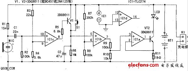
The original circuit diagram of the voice control delay LED lamp control circuit