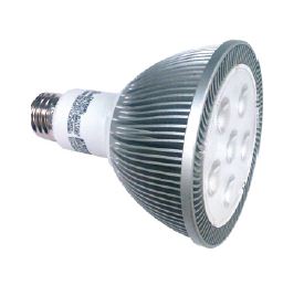
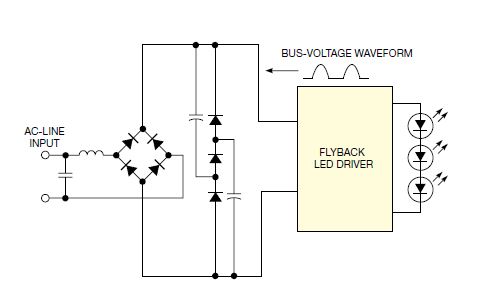
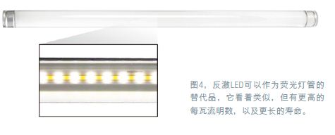
LED luminaires and light bulbs are now rapidly replacing incandescent, halogen and CFL (micro fluorescent) sources in many general lighting applications. Flyback DC/DC converters are the power supply architecture of choice for most LED drivers because these devices enable isolation between the LED and the AC line, which is a safety requirement for most LED lamps. Almost all direct-change LED bulbs have a large aluminum heat sink that is shaped to match the design and has many fins to extend the surface area. High-brightness LEDs have high heat and must be dissipated into the surrounding air to prevent overheating and prolong service life. Although the LEDs themselves are not accessible, they are usually electrically connected to the heat sink because any spacer between them is equivalent to a thermal barrier. The design of the isolator requires thinning the heat sink to reduce this barrier, but does not provide reliable electrical isolation. Therefore, engineers often prefer to use isolated flyback drivers instead of simpler but non-isolated buck structures. Flyback LED drivers also have the ability to be simple, low cost, and achieve high power factor; and add some circuitry to be compatible with popular TRIAC (three-terminal AC) dimmers. Figure 1. The core component of the flyback LED driver circuit is a coupled inductor. The core component of the flyback LED driver circuit is a coupled inductor (Figure 1). Large voltage MOSFETs are used to switch the inductor primary on the DC bus. When the switch is turned on, the current in the inductor rises and the energy is stored as a magnetic field. For this reason, the inductor core requires an air gap. The switching of MOSFT interrupts the primary current; therefore, current must flow into the secondary winding rather than through the diode and into the output capacitor and load. During this time, the energy in the inductor is transferred to the output. Since the current does not flow to the output when the MOSFET is on, a storage capacitor is required at the output to provide continuous current to the LED. The turns ratio of the inductor makes the transformer neither buck nor boost; it must consider the reflected voltage that appears on the primary winding when the MOSFET is turned off. The voltage at the drain of the MOSFET must not exceed its maximum rated drain-to-source voltage at peak line voltage conditions, as well as the maximum LED output voltage. This voltage is equal to the DC bus voltage plus the LED output voltage, multiplied by the turns ratio, which is the reflected voltage. For a 120V AC circuit, the MOSFET should have 400V; for a 277V AC or wide input range circuit, the MOSFET should have 650V. At these voltages, a practical inductor design that requires less secondary turns can be made. The flyback converter continuously stores and delivers energy through the inductor. Therefore, the inductor only works in one quadrant on the magnetic flux density and magnetic field strength curves. Thus, the core must be large to deliver the power provided by other more complex power structures, which are more efficient for core utilization. The flyback solution is more suitable for power levels less than 50W, which covers all screw-switched LED bulbs, as well as many spotlights and floodlights (Figure 2). Flyback designs can also operate at higher power levels; however, these designs are more complex, often using multiple inductors, as well as MOSFET interleaving circuits. Figure 2. The flyback solution is best suited for applications with less than 50W of power consumption, covering all screw-on direct-change LED bulbs, as well as many spotlights and floodlights. As performance standards gradually cover LED lighting products, environmental considerations have become a requirement, such as high power factor. The flyback LED driver can provide a power factor of about 0.9. It uses passive circuit technology without any pre-conditioning stage that adds significant cost and size. In order to provide a high power factor, the flyback circuit can be operated from a full-wave rectified DC bus, using only a small number of capacitors for high frequency coupling, or a simple passive valley fill circuit consisting of two capacitors and three diodes can be added ( image 3). The first method is cheaper, but the output requires a larger holding capacitor to prevent the LED current from falling near the zero crossing of the AC line. Therefore, this method is only feasible if the LED is 350 mA or less. The second method is the more common method, which adds some cost but overcomes the limitations of the first method. Figure 3, in order to provide a high power factor, can use only a small capacitor for high-frequency coupling, run the flyback circuit from a full-wave rectified DC bus, or add a simple two capacitor and three diodes Passive valley filling circuit The next question to consider is how to adjust the LED current. This adjustment can be achieved using a secondary voltage and current sensing circuit that uses an optocoupler to pass the feedback signal back to the primary side control IC. Alternatively, the peak current at the primary side can be adjusted only in the MOSFET without directly detecting the voltage or current of the LED. Another option is to use a primary detection method that provides some current regulation and overvoltage protection, but does not require an optocoupler. The use of secondary voltage and current sensing circuits is the most accurate method, but it requires the use of optocouplers and an output sense and voltage regulator circuit, all of which affect space and cost. Adjusting the primary-side peak current in the MOSFET saves a lot of components, but the control accuracy is low, and the correct output current can only be provided at some line input and LED output voltage. Although this approach may be acceptable for some low-end applications, it does not provide protection against open circuit conditions. If the load is open, the output of a flyback conversion may generate a high voltage, for example, when one of the strings of LEDs fails open, because the voltage continues to rise until the inductor can discharge its stored current. Manufacturers now use a primary detection method in the smart flyback control IC to detect the current and voltage at the primary side of the circuit and use an algorithm to determine the output current without having to detect it directly. An LED driver using this controller can provide a stable output current over an input voltage ramp, but its output still needs to be set for a certain number of LEDs because it does not regulate voltage variations. Such controllers may also include circuitry to detect open circuit conditions to limit the output voltage. This method is more accurate than the method of adjusting the peak current of the primary side of the MOSFET because the controller has higher complexity, but still weaker than the secondary voltage and current detection circuit using the optocoupler. The flyback driver in the LED bulb can be any PFC technology. However, the current trend is that users can use the installed TRIAC dimmer. This approach adds more complexity to the LED driver design. TRIAC dimmers typically operate poorly on capacitive loads such as solid state power converter circuits because when the TRIAC is ignited, the current is continuously turned on only when the current remains above a predetermined threshold. In LED drivers, some extra circuitry is typically required to ensure this activity. Without these additional circuits, the ignition of the TRIAC will be irregular, causing flicker. After solving this problem, the LED driver must also be able to adjust the LED's output current based on the position of the dimmer. The most basic circuit depends on the bus voltage drop when the dimmer level drops causing the output current to decrease. However, this solution offers limited performance and can only be used for a portion of the dimmer's adjustment range. Perhaps a better dimmer designed to work with LED drivers is more important than designing more complex LED drivers and adapting them to dimmers originally used for fluorescent lamps. Although this scheme seems to have technical logic, the market has not adopted this direction now. Many designs now offer good dimming control by adding a TRIAC firing angle detection circuit and converting it to a DC control voltage and then adjusting the output current accordingly. However, this type of solution now requires a lot of components because they use a method of adjusting the peak current at the primary side in the MOSFET, which usually requires multiple optocouplers. Therefore, the price of such products is at least $30. The next-generation dimmable flyback design is likely to use a primary detection method, provided that new, smarter control ICs are introduced into the market. In addition to being used for floodlights and spotlights, flyback LEDs can also be used as a replacement for fluorescent lamps. They look similar, but LEDs have higher lumens per watt and longer life (Figure 4). For example, you can connect a LED in a chain to make it appear as a continuous source. The figure uses a 24W LED to replace the 32W T8 fluorescent lamp. At this level, the flyback design provides the best option for low-cost drives that meet both safety and performance requirements. Figure 4 For this type of LED illumination, compatibility with TRIAC dimmers is generally not required. It typically uses analog dimming control from 0V to 10V, or digital control using DALI (Digital Addressable Lighting Interface) in more advanced applications. method. This solution eliminates many dimming problems and enables finer control of the light output because it can be PWM, linear dimming, or both. Automobile Aluminum Alloy Die Casting Automobile Aluminum Alloy Die Casting,Auto Alloy Die Casting,Aluminium Alloy Die Casting,Aluminum Profile Auto Processing Dongguan Metalwork Technology Co., LTD. , https://www.dgdiecastpro.com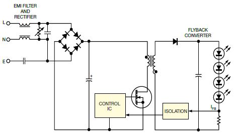
1 time
Window._bd_share_config = { "common": { "bdSnsKey": {}, "bdText": "", "bdMini": "2", "bdMiniList": false, "bdPic": "", "bdStyle": " 0", "bdSize": "24" }, "share": {}, "image": { "viewList": ["qzone", "tsina", "tqq", "renren", "weixin"], "viewText": "Share to:", "viewSize": "16" }, "selectShare": { "bdContainerClass": null, "bdSelectMiniList": ["qzone", "tsina", "tqq", "renren" , "weixin"] } }; with (document) 0[(getElementsByTagName('head')[0] || body).appendChild(createElement('script')).src = 'http://bdimg.share. Baidu.com/static/api/js/share.js?v=89860593.js?cdnversion=' + ~(-new Date() / 36e5)];