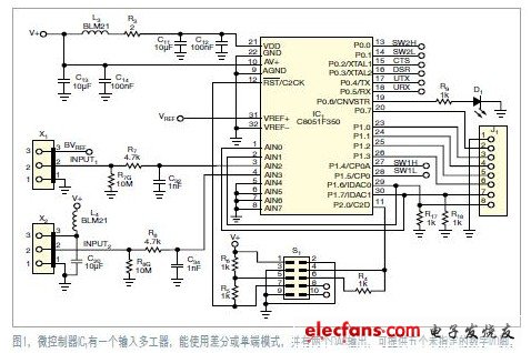
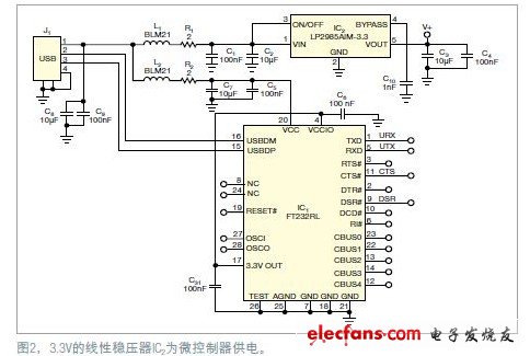
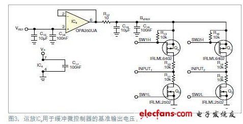
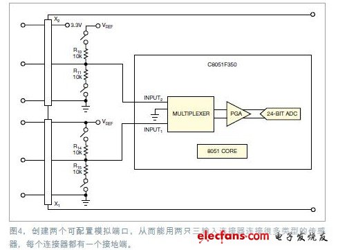
The circuit in this design includes a mixed signal microcontroller, a USBUART (Universal Asynchronous Receiver / Transmitter), and a novel adaptive analog sensor input circuit. This circuit can connect various types of sensors to the two analog input channels designed, control these devices on a USB host, and read out the measurement data. The USB connection provides power to the circuit. Simple commands can be used to control the device on the computer; even the terminal software can do the measurement work. The 8051 core has free tools for programming, such as IDE (Integrated Development Environment), debugger and C compiler. This design uses an 8051-based microcontroller with a price of $ 8, a PGA (programmable gain amplifier), and a 24-bit Σ-Δ ADC (Figures 1, 2 and 3). The microcontroller IC1 has an input multiplexer, which can be used in differential mode or single-ended mode. It also has two DAC outputs that can provide five unspecified digital I / O pins (Figure 1). One output pin drives D1 under program control. The other digital pins are used to configure two analog input ports. In addition, the reference output of the microcontroller can also be sent to a certain analog input port. The remaining four digital pins are connected to the USB UART chip. schematic diagram The 3.3V linear regulator IC2 powers the microcontroller (Figure 2). From the USB port through the magnetic beads and filter, you can directly power the USB chip IC1. This chip is a common and reliable USBUART chip that can communicate with computers using any operating system. Op amp IC4 is used as a buffer for the microcontroller's reference output (Figure 3). Schematic diagram of op amp IC Using two three-input connectors, you can connect many types of sensors to two configurable analog ports, and each connector has a ground (Figure 4). One ground terminal provides 3.3V power, and the other outputs a buffered reference voltage with a rating of 2.5V. The middle pin of the two connectors is connected to the analog input multiplexer of the microcontroller. In this way, both single-ended voltages can be measured, or the two connectors can be used as differential inputs. Both inputs have independently switched pull-up and pull-down resistors R10, R11, R14 and R15. Scooter Charger,Fast Charger For Scooter,Scooter Battery Charger,Smart Charger For Scooter HuiZhou Superpower Technology Co.,Ltd. , https://www.spchargers.com