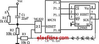
The Watchdog circuit is one of the anti-interference measures required by embedded systems. In this paper, a new watchdog circuit is designed with X25045 chip. It has the characteristics of small size, low I/O line and convenient programming. It can be widely used in instrumentation and various industrial control systems. Foreword When the industrial control system is running, it usually encounters various kinds of on-site interference. The anti-interference ability is an important indicator to measure the performance of the industrial control system. The Watchdog circuit is an important guarantee for self-monitoring system operation. Almost all industrial control systems include a watchdog circuit. In the 8096 series MCU and the enhanced 8051 series MCU, the system has been implemented inside the chip, and the user can open it with software, which is convenient to use. However, at present, the industrial control system is still using the cheap ordinary 8051 series MCU, and the watchdog circuit must be established by the user himself. The watchdog circuit generally has two kinds of software watchdogs and hardware watchdogs. The software watchdog does not require an external hardware circuit, but the system needs to sell a timer resource, which is difficult to do in many systems, and if the system software is not working properly, it may cause the watchdog system to crash. The hardware watchdog is a real "program operation monitor". For example, the counting type watchdog circuit usually consists of 555 multivibrator, counter and some resistors and capacitors. The system circuit composed of discrete components is more complicated. The operation is not reliable enough. Introduction to X25045 chip X25045 is a standardized 8-pin integrated circuit produced by Xicor Corporation of the United States. It combines EEPROM, watchdog timer and voltage monitoring into a single chip, which greatly simplifies hardware design, improves system reliability and reduces The space requirements for the printed circuit board, reducing the cost and system power consumption, is an ideal microcontroller peripheral chip. The X25045 pin is shown in Figure 1. Figure 1 X25045 pin diagram Its pin function is as follows. CS: slice selection input; SO: serial output, data is output bit by bit from this pin; SI: serial input, data or command is written to the X25045 bit by bit from this pin; SCK: serial clock input, its rising edge will write data or command, and the falling edge will output data; WP: Write protection input. When it is low, the write operation is disabled; Vss: ground; Vcc: power supply voltage; RESET: Reset output. Before the X25045 reads and writes, it needs to issue instructions to it. The instruction name and instruction format are shown in Table 1. Table 1 X25045 instructions and their meanings X25045 watchdog circuit design and programming The X25045 hardware connection diagram is shown in Figure 2. The X25045 chip contains a watchdog timer that allows the system to monitor the system's monitoring time. If there is no bus activity during the preset time of the watchdog timer, the X25045 will output a high level signal from RESET, and output a positive pulse through the differential circuits C2 and R3 to reset the CPU. In the circuit of Figure 2, there are three reset signals of the CPU: power-on reset (C1, R2), manual reset (S, R1, R2) and Watchdog reset (C2, R3), which are added to the RESET terminal through the OR gate. The time constants of C2 and R3 do not have to be too large, and there are hundreds of microseconds, because the oscillator of the CPU is already working. Figure 2 X25045 watchdog circuit hardware connection diagram The preset time of the watchdog timer is set by the corresponding bit in the status register of the X25045. As shown in Table 2, the X25045 status register has 6 bits of meaning, of which WD1 and WD0 are related to the watchdog circuit, and the remaining bits are related to the working settings of the EEPROM. Table 2 X25045 Status Register WD1=0, WD0=0, preset time is 1.4s. WD1=0, WD0=1, preset time is 0.6s. WD1=1, WD0=0, preset time is 0.2s. WD1=1, WD0=1, the watchdog is prohibited from working. The timing of the watchdog circuit can be determined by the cycle time of the specific application, usually slightly longer than the maximum cycle time during normal operation of the system. When programming, you can add a dog feed instruction in the appropriate place of the software, so that the watchdog's timing time will never reach the preset time, and the system will not reset and work normally. When the system runs away and cannot be captured back by software traps or other methods, the watchdog timing time quickly increases to the preset time, forcing the system to reset. 72V 60Ah Power Battery,Portable Energy Battery,Electric Mobility Battery,Energy Storage System Sichuan Liwang New Energy Technology Co. , https://www.myliwang.com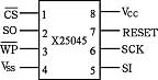
![]()