Research and Application of New Hybrid Electric Vehicle Testing Technology The rapid development of the automotive industry has promoted the development of the automotive electronics industry. As a new development direction of the automotive industry, hybrid electric vehicles (HEVs) have received national attention. From the aspects of technology, energy-saving and emission-reduction effects, industrialization capabilities, and other aspects, hybrid power has the advantages of traditional internal combustion engines and electric motors, and will occupy advantages for a long period of time. Hybrid vehicle technology avoids the deficiencies of pure electric vehicles in battery technology and energy infrastructure, and has become a hot spot for recent research and development of new vehicles. After the support and development of the National "863 Program", China's hybrid vehicle technology is rapidly moving towards industrialization. This article studies hybrid vehicles, systematically analyzes the core technologies of various important components of hybrid vehicles, and proposes an economical and practical design example of a hybrid vehicle control system. The system adopts advanced computer technology and bus technology, integrates intelligent control, signal acquisition, data processing and communication, and has good real-time control, which realizes the effective integration of vehicle control intelligence and multi-sensor. Hybrid vehicles need to determine their corresponding control strategies based on different driving conditions and real-time parameters of the power battery. The "power control strategy system" analyzes and processes the data from the operating condition monitoring system, judges that the motor at this time should be in the engine working mode, the power battery working mode, or the cooperative working mode, and then issues the corresponding control command. Studies have shown that a good system control strategy should be to make the engine work at 50% to 65% of its maximum load, while taking into account the dynamics of the car. An important basis for strategic control is the SOC value of the power battery. When the SOC value is in the normal operating area (30% to 75%), the discharge current of the power battery is in the range of 20 to 65 A. If the driver requires acceleration of the vehicle at this time Less than 30%, power battery can be used to drive the vehicle. When the driver's request for acceleration is 30% to 65%, the excess energy released by the engine at this time can be used to charge the power battery. When the driver's requirement for acceleration is 65% ~ 80%, the engine independently drives the car until it reaches its maximum output power. When the acceleration requirement is greater than 80%, the vehicle can be driven by both the engine and the power battery. In addition, the safety and life of the power battery need to be considered. When the SOC value changes beyond the above range, the corresponding control command needs to be issued in a timely and reasonable manner. When the SOC is greater than 80%, the power battery is forcibly discharged, and the control system needs to change the ratio of the power mixing degree at this time to increase the power battery's ratio to the total output power. At this time, the rich energy generated by the engine is not recovered. When the SOC is less than 20%, the power battery enters the forced charging mode. At this time, a part of the output power of the engine is used to charge the power battery, and the car is completely driven by the engine at this time. 3.1 Signal channel After the processor system processes the collected signals, it is sent to the upper-layer power strategy control system, and the upper-layer control signals are also transmitted to the lower layer. This system uses two CAN transceivers to accomplish this task. Using CAN bus technology, not only free networking, strong scalability, good real-time, high reliability, but also has self-diagnosis and monitoring capabilities, it is a very effective communication method. The CAN bus has the following characteristics: 4 Conclusion The increase in fuel costs and the increased awareness of environmental protection make hybrid power no longer a synonym for high cost. At present, there are no hybrid vehicles with independent property rights in China. Therefore, the research on hybrid vehicles in this paper not only provides some experience for the research work of domestic counterparts, but also has the effect of breaking the monopoly of foreign technology. Features, I believe that the market for the use of hybrid power will become larger and larger, and the application prospects will become wider and wider. Applied in industries such as automobiles, telecommunications, electronics, and healthcare Dongguan Bofan technology Co., LTD , https://www.ufriendcc.com
1 Hybrid control system There are three key factors for hybrid vehicles: a system that can monitor the operating status of the vehicle in detail; analyze the information obtained by the monitoring system and issue corresponding control commands; compared to general electronic systems, hybrid vehicle electronics The control system works in a very harsh environment in the car, electromagnetic interference, vibration, dust, etc. will cause technical bottlenecks, as shown in Figure 1. 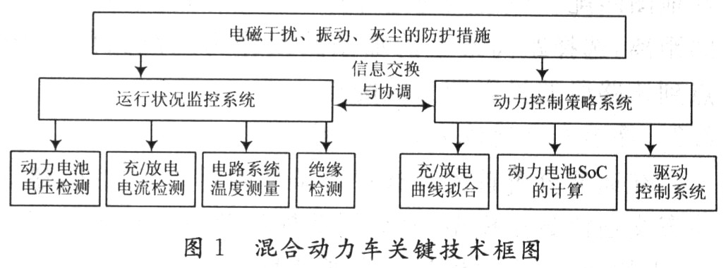
2 Power control strategy system The hybrid electric vehicle is powered by the engine and the battery. The engine and the motor can be combined in different ways to obtain different driving schemes, such as series, parallel, and hybrid. The performance of the vehicle is not only related to the engine and electric motor, but also related to its control strategy and optimization method. According to the way of energy combination, hybrid electric vehicles can be divided into series hybrid electric vehicles (SHEV) and parallel hybrid electric vehicles (PHEV) according to the power driving mode. The research object of this article is SHEV. The characteristics of SHEV are suitable for the conditions of frequent starting, acceleration and low-speed operation in urban driving, which can make the engine run stably near the optimal operating point, and adjust the speed of the vehicle by adjusting the output of the battery and the motor, thereby improving the complexity The fuel economy of vehicles driving down while reducing emissions. When the battery's state of charge (SOC) is high, the engine can be turned off, and only the motor can be used for power output, so that the engine can avoid running at idle and low speed, improve the efficiency of the engine, and reduce the emission of harmful substances. The structure of SHEV is shown in Figure 2. 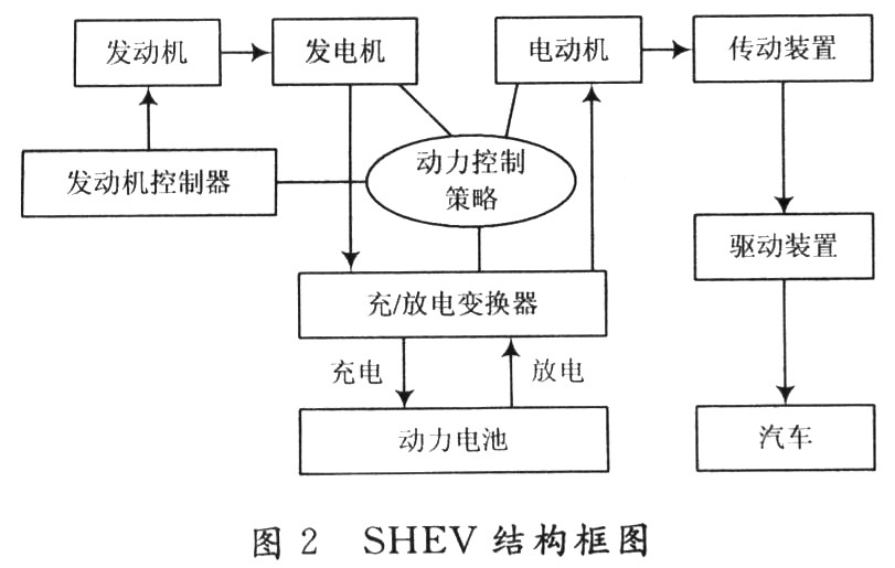
3 Operating condition monitoring system "Operating condition monitoring system" is capable of collecting the current, voltage, and temperature of the power battery, as well as the vehicle's braking signal, clutch pressure signal, and driving speed. Accurately acquiring these signals is the key to achieving hybrid driving vehicles Where. Figure 3 is a structural block diagram of the "operational installation monitoring system". The system uses two TLE4275 and one LM2577 as the power supply module of the system. The input voltage is 6 to 18 V, which can meet the paralysis of the monitoring system caused by the unstable battery output voltage caused by vehicle startup and special circumstances. 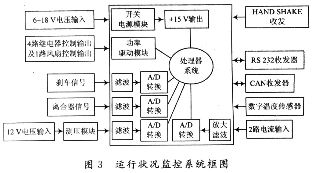
(1) Non-destructive bus arbitration based on priority competition;
(2) Multi-address frame transmission with the aid of reception filtering;
(3) With error detection and automatic retransmission of error frames;
(4) The data transmission method can be divided into data broadcast type and remote data request type.
In addition, the system also has an RS 232 transceiver, which is mainly used for debugging in the design process and quality inspection in the product production process.
3.2 Measurement of battery voltage and temperature The measurement method of power battery voltage depends on the specific situation of power battery. This system uses nickel-metal hydride batteries, which can be divided into 12 groups of batteries, each group of batteries includes 10 small batteries, each battery The voltage is 1.2 V, so the voltage of each group is 12 V and the total voltage is 144 V. In order to ensure that the measurement system is suitable for different working conditions, especially considering that the battery voltage will rise appropriately during charging, the voltage may reach 20 V under special circumstances, so the designed measurement range should be 0 ~ 20 V.
The temperature measurement uses the digital temperature sensor DS1860, which can use multiple sensors, a total of a data line and a power line and a ground line, with the advantages of simple operation and less input port.
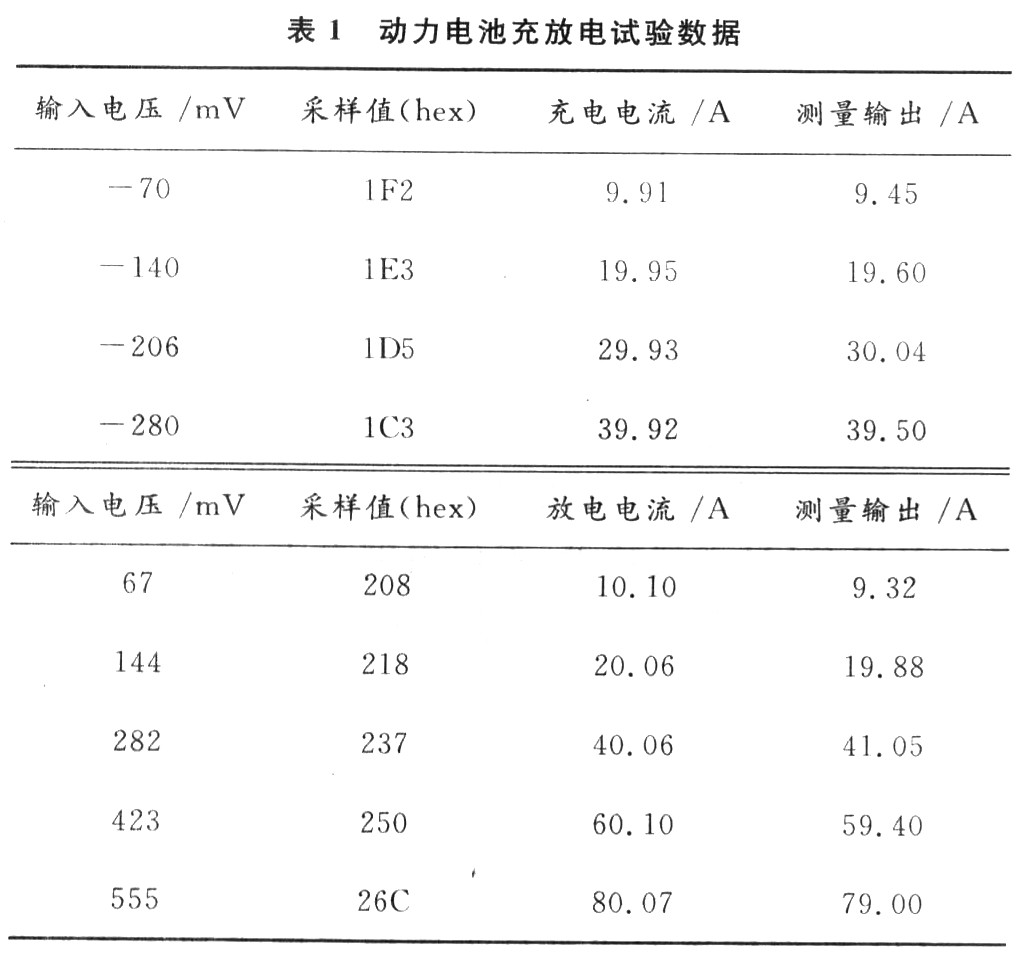
3.3 Charge and discharge current measurement Two methods can be used to measure the large current of charge and discharge of the power battery. The most common one is the Hall sensor. Therefore, choosing the right Hall sensor is the key to accurately measuring the circuit. The magnetic field sensitivity of the Hall sensor or the starting point of the magnetic field should match the motor model and structure. Different motor models and different motor design structures have different magnetic field distributions and fluctuations in the magnetic field of the rotor. If the magnetic sensitivity of the Hall sensor is too high or too low, due to the irregular fluctuation of the magnetic field distribution of the rotor magnetic steel and the magnetic steel gap, it will cause the position sensor to give the wrong signal. In addition, the anti-static capability of the Hall sensor chip, the anti-surge voltage or anti-surge current capability of the Hall sensor chip must also be considered. The system studied in this paper adopts Hall sensor of model UGN3503UA. In the design of the measuring circuit, it should be noted that the output of the sensor is milliampere-level current, so it is necessary to select an appropriate input resistance to convert it into a voltage signal, and use a highly accurate amplification and sampling circuit. Table 1 is an experiment result of this system.