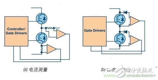
The overall market trend for industrial motor drives is the ever-increasing demands for greater efficiency and reliability and stability. Some trade-offs to increase the conduction loss of insulated gate bipolar transistors (IGBTs) are: higher short-circuit current levels, smaller chip sizes, and lower thermal capacity and short-circuit withstand times. This highlights the importance of gate driver circuits and overcurrent detection and protection. The following discusses the successful and reliable implementation of short-circuit protection in modern industrial motor drives, while providing an experimental example of an isolated gate driver for three-phase motor control applications. What are the short circuits in the industrial environment? Industrial motor drives have a relatively harsh operating environment and can experience high temperatures, AC line transients, mechanical overloads, wiring errors, and other unexpected conditions. Some of these events may cause large overcurrents to flow into the power circuit of the motor drive. Figure 1 shows three typical short circuit events. Figure 1. Typical short circuit event in industrial motor drive They are: The inverter is straight through. This may be caused by incorrectly turning on two IGBTs of one of the inverter arms, which may be due to electromagnetic interference or controller failure. It may also be caused by one of the IGBT wear/faults on the arm, while the normal IGBT remains switched. Short circuit to phase. This may be caused by a performance breakdown, excessive temperature or an overvoltage event that causes an insulation breakdown between the motor windings. The phase line is shorted to ground. This may also be caused by a performance breakdown, excessive temperature or an overvoltage event that causes an insulation breakdown between the motor windings and the motor casing. In general, the motor can absorb very high currents for a relatively long period of time (ms to seconds, depending on the size and type of the motor); however, the IGBT, the main part of the industrial motor-driven inverter stage, is short-circuited. The tolerance time is in the order of microseconds. IGBT short circuit withstand capability The IGBT short-circuit withstand time is related to its transconductance or gain and the thermal capacity of the IGBT chip. Higher gains result in higher short-circuit currents within the IGBT, so it is clear that lower gain IGBTs have lower short-circuit levels. However, higher gains also result in lower on-state conduction losses, and trade-offs must be made. 1 The development of IGBT technology is contributing to the increase in short-circuit current levels, but the tendency to reduce short-circuit withstand time. In addition, advances in technology have led to smaller chip sizes, 2 reduced module size, but reduced thermal capacity, and further shortened tolerance times. In addition, it has a large relationship with the IGBT collector-emitter voltage, so the parallel trend of industrial drive tends to higher DC bus voltage levels further reduces the short circuit withstand time. In the past, this time range was 10 μs, but in recent years the trend has been in the direction of 5 μs3 and under certain conditions down to 1 μs. 4 In addition, the short-circuit withstand time of different devices is also quite different, so for IGBT protection circuits, it is generally recommended to build more margin than the rated short-circuit withstand time. IGBT overcurrent protection Regardless of property damage or safety considerations, IGBT protection for overcurrent conditions is the key to system reliability. IGBTs are not a fail-safe component. If they fail, they can cause the DC bus capacitor to explode and cause the entire driver to malfunction. 5 Overcurrent protection is typically achieved by current measurement or desaturation detection. Figure 2 shows these tips. For current measurement, both the inverter arm and the phase output require measurement devices such as shunt resistors to handle shoot-through faults and motor winding faults. The fast execution trip circuit in the controller and / or gate driver must turn off the IGBT in time to prevent the short circuit withstand time. The biggest benefit of this method is that it requires two measuring devices on each inverter arm and is equipped with all relevant signal conditioning and isolation circuits. This can be alleviated by simply adding a shunt resistor to the positive DC bus line and the negative DC bus line. However, in many cases, there are either arm shunt resistors in the driver architecture or phase shunt resistors to serve the current control loop and provide motor overcurrent protection; they are also possible for IGBT overcurrent protection – provided that The signal conditioning response time is fast enough to protect the IGBT during the required short-circuit withstand time. Figure 2. Example of IGBT overcurrent protection technology The desaturation detection uses the IGBT itself as a current measuring element. The diodes in the schematic ensure that the IGBT collector-emitter voltage is only monitored by the sense circuit during turn-on; during normal operation, the collector-emitter voltage is very low (typically 1 V to 4 V). However, if a short circuit event occurs, the IGBT collector current rises to a level that drives the IGBT out of the saturation region and into the linear operating region. This causes the collector-emitter voltage to rise rapidly. The above normal voltage levels can be used to indicate the presence of a short circuit, while the desaturation trip threshold level is typically in the 7 V to 9 V region. Importantly, desaturation can also mean that the gate-emitter voltage is too low and the IGBT is not fully driven to the saturation region. Be careful when performing desaturation detection deployment to prevent false triggering. This may especially occur during the transition from the IGBT off state to the IGBT on state when the IGBT has not fully entered saturation. The blanking time is usually between the turn-on signal and the desaturation detection activation time to avoid false detections. A current source charging capacitor or RC filter is also typically added to create a short time constant in the detection mechanism to filter the filter spurs caused by noise pickup. When selecting these filter components, a trade-off is required between the noise immunity and the IGBT short-circuit withstand time. Rechargeable Battery & Charger Battery Zhejiang Baishili Battery Technology Service Co,.Ltd. , https://www.bslbatteryservice.com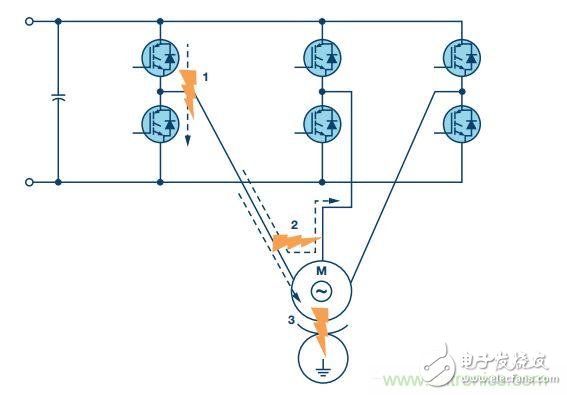
This paper mainly discusses the successful and reliable implementation of short-circuit protection in modern industrial motor drives, and provides an experimental example of an isolated gate driver for three-phase motor control applications. Welcome children's shoes of interest to learn!