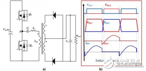
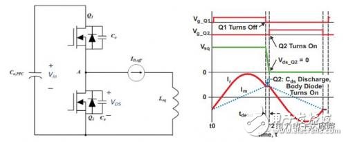
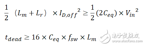
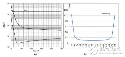
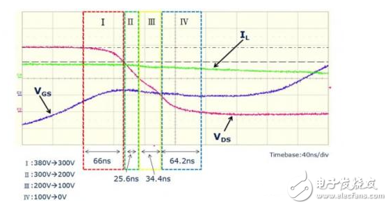
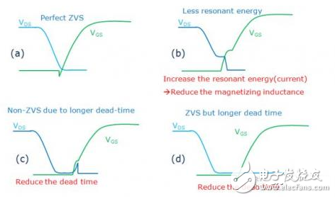
One of the advantages of LLC is the ability to achieve zero-voltage turn-on (ZVS) of the primary MOSFET over a wide range of loads, and the turn-on loss of the MOSFET is theoretically reduced to zero. To ensure the ZVS of the LLC primary MOSFET, the following three basic conditions must be met: 1) 50% duty cycle of the upper and lower switch tubes, 1800 symmetrical drive voltage waveform; 2) Inductive resonant cavity and sufficient inductive current; 3) Have enough dead time to maintain ZVS. Figure a) is a typical LLC series resonant circuit. Figure b) is the operating waveform of the MOSFET under inductive loading. Due to the inductive load, the current phase will lead the voltage, thus ensuring the ZVS of the MOSFET operation. To ensure that the MOSFET is operating in the inductive region, the resonant current on the resonant inductor must be large enough to ensure that the charge stored on the equivalent parasitic capacitance between the source and drain of the MOSFET can be completely released during the dead time. When the primary MOSFET is in the off state, the resonant current in the series resonant circuit charges and discharges the equivalent output capacitance of the switching transistor MOSFET. The equivalent circuit when the MOSFETs are turned off is shown below: By analyzing the above figure, we can get two necessary conditions to meet ZVS, as follows: The formula looks simple, however, the actual situation of the MOSFET equivalent output capacitance Ceq is that the equivalent parasitic capacitance of the MOSFET is a function of the source-drain voltage Vds. The previous article gave a detailed theory of the equivalent parasitic capacitance of the MOSFET. And actual introduction. That is, the magnitude of the equivalent capacitance value will vary with Vds. As shown in the figure below, take Infineon's IPP60R190P6 as an example: The Vds discharge process of the LLC series resonant circuit MOSFET is divided into four stages, as shown in the following figure, (I) 380V-300V; (II) 300V-200V; (III) 200V-100V; (IV) 100V-0V. It can be seen from the figure that the two parts (I) and (IV) occupy nearly 2/3 of the Vds discharge time, and the inductor current of the resonant cavity is substantially unchanged. The main reason why these two parts occupy most of the Vds discharge is that the parasitic capacitance Coss between the source and drain of the MOFET increases exponentially as Vds drops to near zero. Therefore, to completely release this portion of the charge, a longer LLC resonance period and release time are required. Therefore, choosing the right MOSFET (sufficiently small equivalent parasitic capacitance) is critical to the implementation of ZVS, especially when Vds is close to zero, the equivalent output capacitance is small enough to further reduce the dead time and Improve the efficiency of LLC. The figure below further illustrates how to choose the right ZVS solution. Figure (a): Ideal ZVS waveform; Figure (b): Vds has not dropped to 0, and Vgs has appeared. In this case, a hard switching occurs in the LLC series resonance. The countermeasures need to reduce the excitation current of the transformer, or increase the dead time appropriately (if the IC is selected, the dead time is generally fixed); Figure (c): ZVS is implemented, but the current in the cavity is not sufficient to maintain the continuous conduction of the diode in the MOSFET. Figure (d) The dead time is too long, which will reduce the efficiency of the entire LLC. In summary, the equivalent output capacitance of the MOSFET is critical to the implementation of the LLC primary MOSFET ZVS. If the MOSFET is already selected, the cavity needs to be carefully calculated, debugged, and set, and the appropriate dead time is chosen to cover the application range of all loads. In practical applications, the hard switch for steady-state operation can be modified by design to achieve stable operation design. However, the hard switch during the boot process (soft start to high frequency to low frequency process), especially the first few switch cycles during the boot process, for some designs and solutions, hard switches can not be avoided. Li-Ion 36V Battery,Lithium Ion 36V Battery,Lithium Ion Battery 36V 20Ah,36V Lithium Marine Battery, Super Batteries,LFP Battery, High rate lithium battery Langrui Energy (Shenzhen) Co.,Ltd , https://www.langruibattery.com