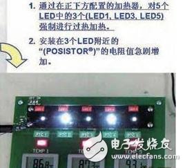
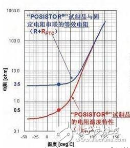
As the performance of LED lighting equipment (light-emitting diodes) continues to increase and prices are becoming cheaper, the market is rapidly expanding. LED lighting equipment has been reduced in price. However, compared with traditional incandescent lamps and fluorescent lamps, the performance as lighting equipment is still poor, and people point out their safety issues. Although the LED has high-efficiency illumination and low power consumption, the high-brightness LED component itself is in an abnormally high temperature state. This article will introduce the method of using Murata's ceramic PTC thermistor "POSISTOR" to simply realize the overheating protection of LED lighting equipment, which can achieve low cost and improve the safety of LED lighting equipment. Demo board description Figure 1: Light-emitting diode (LED) demonstration board exhibited by Murata Manufacturing Co., Ltd. Five surface mount LEDs were mounted on the LED demo board, and a small ceramic heater was placed on the back of the board directly below. The liquid crystal display shows the board temperature near the LED. The photo at the bottom right indicates that the heater on the back of the board forcibly heats the LED. The temperature near the LED reaches 80 ° C or higher, and the brightness of the overheated LED is greatly reduced. This is due to the action of the PTC thermistor "POSISTOR" installed near the LED, and the current flowing through the LED is limited. In this way, when the LED itself is abnormally heated or the temperature around the LED is abnormally increased due to external reasons, by reducing the brightness of the LED, the LED can be prevented from continuously heating, thereby preventing the occurrence of serious events such as smoke and burning of the lighting device. Figure 2 is a circuit diagram of such an LED demonstration board. A constant voltage of 5V was applied to the five parallel LEDs. The resistor (R) and "POSISTOR" (RPTC) are fixed in series with the LED through a dual transistor whose combined resistance (R and RPTC) defines the maximum current flowing through the LED. The transistor has the function of controlling the potential of "A", thereby turning on and off the current flowing through the LED, and relying on PWM control for brightness adjustment of the LED. When the potential of "A" is "ON", the voltage (VBE) between the base and the emitter of "TR2" of the two transistors is fixed to about 0.7V. Therefore, the value of the current flowing through the LED (ILED) is determined only by the series resistance (R+RPTC). For example, at a temperature of 250 ° C, the resistance (R ten RPTC) is 3.5 Ω, and the current of the LED is 200 mA. Why does the brightness of the LED on the right side of Figure 1 drop dramatically once the temperature is reached? We will explain this through Figure 3. Figure 3: Resistance temperature characteristics and temperature of the LED current relative to the "POSISTOR" prototype Mounted on the LED demo board is a patch-type "POSISTOR" prototype, which has a resistance of 0.5 Ω when the temperature reaches 25 °C. "POSISTOR" is a ceramic thermistor with positive temperature coefficient characteristics. It is characterized by a rapid increase in resistance of more than 1000 times at a given temperature. The resistance and temperature characteristics of the "POSISTOR" prototype are shown on the left. Since the 3.0Ω fixed resistor (R) and the “POSISTOR†resistor ((RPTC) are connected in series on the LED demo board, the equivalent resistance (R 10 RPTC) will also change with temperature. This equivalent resistance determines the current flowing through the LED (ILED). As shown in the diagram to the right, if the temperature is below 40 ° C, the LED current is approximately constant, about 200 mA. If the temperature exceeds 40 ° C or more, the current through the LED is effectively limited to 40 mA or less at 80 ° C. As long as the "POSISTOR" is added to the current limiting resistor that determines the LED current, such an overheat protection structure can be constructed. Even if the LED is in a high temperature state for some reason, if such an overheat protection structure is provided, the LED will not heat up even in a state of high brightness. With this simple method, LEDs can be prevented from causing serious events such as smoke and burning. Eliminates the need for complex temperature sensing and decision logic components, as well as LED current control. However, even at high temperatures, the current is not completely cut off, and a certain amount of current (for example, about 40 mA at 80 ° C) flows through the LED. Like lighting equipment, sometimes the light is completely extinguished but it is dangerous, so this feature is most suitable. Further, the allowable current with respect to the ambient temperature of the ordinary LED element is emphasized as a standard. If the operating current exceeds the allowable current, it tends to deteriorate and the life is reduced. If the current can be limited as shown in the right figure of Fig. 3, current control in accordance with the allowable current curve of the LED element can be achieved. The above example is only a prototype made with "POSISTOR". At present, Murata is developing "POSISTOR" which is most suitable for LED lighting equipment in terms of parameters such as shape, resistance value, and temperature point at which the resistance value rises. Military power supply is accordance with the relevant standard military standards. Jinan Xinyuhua Energy Technology Co.,Ltd , https://www.xyhenergy.com