1 Introduction With the rapid development of Internet technology and multimedia technology, the application of voice communication technology is becoming more and more widely and more and more valued [1]. Today's embedded devices are becoming more complex, with more features than before, and higher and higher performance. In a variety of embedded terminal products, audio processing functions have become an indispensable important component, and high-quality sound effects are an important trend in current development. In this paper, an embedded audio system is designed using ATMEL's AT91RM9200 microprocessor and Philips' UDA1341 stereo audio codec. The hardware part of the embedded audio system adopts the audio system architecture based on IIS bus, and its main hardware circuit is described in detail later. In terms of software, the author takes the embedded Linux operating system as a platform and focuses on the realization of the driver of the audio system under this platform. 2 Introduction to AT91RM9200 processor AT91RM9200 is a new microprocessor based on the ARM920T core introduced by ATMEL for system control and communication [2]. It has great advantages in terms of high performance and low power consumption, and has a high frequency, which can be reached up to 180 MHz. The processor has independent 16K instructions and 16K data cache, full-featured MMU virtual memory management unit, and internal 16KB SRAM and 128KB ROM, EBI interface controller. On-chip integrated rich peripheral interfaces, including network MAC, USB controller, SDRAM controller, CF interface, NAND flash interface, IIC interface, JTAG debugger and support 256 MB of address space. And the processor also provides a bootstrap mode for users to write boot code, which is convenient for the transplantation of Linux and other operating systems. 3 UDA1341TS audio chip and IIS bus profile PHILIPS UDA1341TS is a powerful dedicated voice processing chip [3]. The chip integrates voice amplification, filtering, sampling, A / D and D / A conversion functions, and can perform digital voice processing. The AT91RM9200 processor used in this design has an IIS audio interface, which uses DMA to transfer data. In this way, the DMA controller replaces the CPU to obtain the bus control right, so as to realize the rapid transmission of a large amount of data between different areas between the memory and peripheral devices or memory. Using the DMA interface to transfer data can not only reduce CPU burden, but also save system software design time and reduce programming difficulty. The UDA1341TS supports the IIS bus format and has digital voice processing characteristics, which determines that the circuit connection between the UDA1341TS and the AT91RM9200 processor is relatively simple, and can achieve voice A / D and D / A preprocessing, without the need for additional Add special A / D and D / A devices. It should be noted that digital audio systems require a variety of integrated circuits, so it is very important to provide a standard communication protocol for these circuits. The IIS bus is a digital audio bus protocol jointly proposed by electronic giants such as SONY and PHILIPS. The full name is Inter IC Sound Bus. It is a serial digital audio bus protocol. The bus is specifically used for The data transmission between audio equipment provides a sequence for digital stereo to connect to the standard codec [4]. Currently, many audio chips and processors provide support for the IIS bus. Based on the principle of the IIS bus, the author combines the structural characteristics of the AT91RM9200 processor and the digital audio input / output interface chip UDA1341TS, and the designed embedded audio system can be applied to many similar audio systems. 4 System hardware design Because the IIS bus only processes audio data, other signals such as encoding and control signals are transmitted separately. In order to minimize the number of necessary pins and keep the wiring simple, the IIS bus is composed of 3 signal lines: time division multiplexed data channel lines, field selection lines, and clock signal lines. This system is provided with a clock signal by the system main controller to control the flow of digital audio data between each IC. At this time, the transmitter generates data under the control of an external clock signal and is in slave mode. The hardware connection diagram of this design is relatively simple, as shown in Figure 1. The processor in the picture uses the AT91RM9200 processor, which has a built-in IIS audio bus. The built-in IIS interface can read the data on the IIS bus and is expanded by the UDA1341TS chip. It is connected to the system through the bus and requires the processor to provide the system clock and 3 control lines. The IIS controller of AT91RM9200 is connected to the external audio codec by 5 pins. These pins are: system clock; bit rate clock (can use internal or external clock source); field selection; serial sound input; serial sound output. In this design, UDA1341TS uses the L3 interface, which is used to control the volume and bass of the audio signal. The L3 interface has 3 signals: L3MODE, L3CLK, and L3DATA, and writes bytes to the L3 bus register. The IIS bus controller controls the general-purpose I / O pins of AT91RM9200 through software (the author chooses three general-purpose I / O ports PA0, PA1, and PA2) to support the L3 interface. The following figure is the hardware circuit connection diagram of this embedded audio system, see Figure 2. The connection description of each pin is as follows: SYSCLK: The basic clock source of the IIS bus. The TCLK3 pin of the AT91RM9200 processor is connected to the system clock of the UDA1341TS chip. Since the UDA1341TS chip only supports the slave mode, the system device must provide the system clock in all applications. The system clock frequency is programmable, and its sub-frequency can be 256, 384 or 512 times the sampling frequency. The system clock must be consistent with the digital interface signal in frequency. In the design, I used a 256fs clock. WS: Field selection pin, used to indicate whether the current serial data sampling value is left channel or right channel data. The TK0 pin of the AT91RM9200 processor is connected to WS. BCK: Provide the serial sound bit rate clock used as sampling logic to UDA1341TS. The TD0 pin of AT91RM9200 processor is connected to the BCK pin of UDA1341TS chip. DATAI, DATAO: used to receive and send serial sound data from UDA1341TS, RD0 and RK0 pins of AT91RM9200 processor respectively correspond to the audio input and output pins of UDA1341TS. L3M0DE, L3CLOCK, L3DATA: L3 interface pins of UDA1341TS, respectively connected to the three general data output pins PA0, PA1, PA2 of AT91RM9200. 5 System software design Embedded Linux is a completely open and free operating system. It supports multiple hardware architectures, runs stably, has complete development tools, and provides developers with an excellent development environment [5]. In the embedded Linux system, the device driver provides a software layer (interface) between the application and the actual device, shielding the hardware details for the application. In this design, the audio device driver mainly realizes the transmission of the audio stream through the control of the hardware, while providing a standard audio interface to the upper layer. The entire audio driver program includes device initialization, device opening, digital audio processing (DSP) driver, mixer (MIXER) driver, and release device. Due to space limitations, this article only introduces device initialization and device implementation. Device initialization is the beginning of the entire audio driver, mainly to complete the initialization of UDA1341TS volume, sampling frequency, L3 interface, etc., and register the device. Through the function audio_init (void) to complete the following specific functions: AT91RM9200 control port (PA0, PA1, PA2) initialization; DMA channel allocation for UDA1341TS; initialize UDA1341TS chip; register audio audio equipment and mixer equipment. Given below is the overall framework of the function: audio_init (void) { Set_gpio_ctrl (GPIO_L3CLOCK); / * Initialization of CPU control port * / …… / * “……†means to omit part of the code, the same as below * / Input_stream.dma_ch = DMA_CH1; / * Selection of input DMA channel * / Output_stream.dma_ch = DMA_CH2; / * Output DMA channel selection * / Local_irq_restore (flags); Init_UDA1341 (); / * Initialize UDA1341 * / …… / * The following two functions are used to register audio audio device and mixer device * / Audio_dev_dsp = register_sound_dsp (& at91rm9200_audio_fops, -1); Audio_dev_mixer = register_ound_mixer (& at91rm9200_mixer_fops, -1); } Opening the device is achieved by the function open (), which can complete the following functions: configure the IIS bus interface; set parameters such as UDA1341TS channel and sampling frequency; calculate the buffer size; allocate DMA buffer for UDA1341TS. After the audio module is correctly configured, it can realize the functions of recording, playback and loop playback. This article gives the basic flow of programming to initialize the IIS interface, test the IIS interface, and use the IIS interface to play a piece of music. The flow chart is shown in Figure 3. The design process of recording and looping functions is similar to that of playback, and will not be repeated here. 6 Conclusion This article introduces an embedded audio system based on IIS bus. The system is simple and practical, which can realize the collection and playback of audio. The article specifically describes the hardware connection and embedding of the AT91RM9200 type microprocessor based on ATMEL company and UDA1341TS Realization of Audio Driver under Linux. Of course, this is only the main component of this system. As for other related components such as FLASH and SDRAM, the author has already completed it in the actual design. Due to space limitations, there is no detailed introduction in the article. The system has been implemented on the development platform of AT91RM9200, which can smoothly collect and play audio, and achieved good results. In addition, today's real-time video processing and transmission technology is developing rapidly, and its applications are becoming more and more extensive, such as video conferencing, VOIP phones, etc., the design is appropriately expanded, especially in combination with the video module, it can be applied to more related complex systems .
linear power supply are using pure cooper wire,and it is 24v linear power supply, output voltage 24vac, output current 2A,3A,5A.
power supply unit include indoor and waterproof outdoor series.
High power products, stable, no noise
Features:
Transformer Using pure cooper wire,and 100% enough power output.
Output voltage 24vac, output current 2A,3A,5A.
Output power:48W,72W,120W.
AC input Voltage range: 110V/220VAC±10%, Selected by switch
Wall-mounted type,Easy to install
Good Lightning resistance performance
4 times aging test
Protection: short circuit, over current, overload, over voltage.
3 years warranty
Product application:
Application to PTZ, decoders, ballhead camera, speed dome cameras,fill light,high power AC gun Camera etc
Linear Power Supply Linear Power Supply,Linear Power Supply 12V,Linear Power Supply Schematic,Linear Power Supply Circuit Guangdong Steady Technology Co.LTD , https://www.steadysmps.com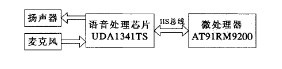
Figure 1 Hardware design diagram 
Figure 2 Connection of hardware circuit 
Figure 3 IIS interface function test software design flow chart