The contact network in rail transit technology mainly includes the following items: 1. Basic components, such as cement pillars, steel pillars and foundations for supporting these structures; 2. Basic installation structural components, the main function of this content is to connect the contact network conductors. And the basic components; 3. Contact the network conductor, this part of the role is to transmit current to the electric locomotive; 4. Other auxiliary components, including the return line, additional suspension and so on. Contact nets, rails and earth, and return lines are collectively referred to as traction nets. First, the introduction Overhead lines are one of the two types of power supply networks commonly used in electrified railways (the only way to supply bus trolley buses); the other is the third rail. There are different titles in different countries and regions: -Overhead contact system (OCS)—Europe, except UKand Spain -Overhead line equipment (OLE or OHLE)—UK -Overhead equipment (OHE) — UK, India, Pakistanand Malaysia -Overhead wiring (OHW)—Australia -Catenary-United States, India, UK, Singapore (NorthEast MRT Line), Canada, France (french:Caténaire) andSpain. It is also known as overhead cable or overhead cable in Hong Kong and Taiwan. composition The catenary is a special form of transmission line that is erected along the railway line and supplies power to the electric locomotive. It consists of contact suspension, support device, positioning device, pillar and foundation. Contact suspensions include contact lines, chords, load-bearing cables, and connecting parts and insulators. The contact suspension is erected on the support by the support device, and its function is to transfer the electric energy obtained from the traction substation to the electric locomotive. Support devices are used to support the contact suspension and transfer its load to the strut or other building. Metro trains vary according to the area where the contact network is located, the station and the large buildings. Supporting devices include wrist arms, horizontal tie rods, suspension insulator strings, rod insulators and other special support equipment for buildings. The positioning device comprises a positioning tube and a positioner, and the function thereof is to fix the position of the contact line, so that the contact line is within the range of the track of the pantograph slide, ensuring that the contact line and the pantograph are not separated, and the horizontal load of the contact line is transmitted to pillar. The struts and foundations are used to withstand the full load of the suspension, support and positioning devices and to secure the contact suspensions at specified locations and heights. The Chinese contact net uses prestressed reinforced concrete pillars and steel columns. The foundation is for the steel pillars, that is, the steel pillars are fixed on the basis of the reinforced concrete below, and the entire load transmitted by the foundation is supported by the foundation. The stability of the pillars. The prestressed reinforced concrete pillars are made in one piece with the foundation, and the lower end is directly buried in the ground. Voltage level The voltage level of the contact network: between 25KV and 30KV (for ground) single-phase power frequency AC, the voltage of the electric locomotive is: 25KV. Considering the voltage loss, the output voltage of the traction substation is: 27.5KV or 55KV, of which 55KV is the AT power supply mode, which is mainly used in high-speed electrified railways. The contact network voltage of urban rail transit is generally 750V or 1500V DC. Second, the type Classification of contact nets Most are distinguished by the type of contact suspension. The classification of the contact suspension we are talking about is for each anchor segment of the catenary. There are many types of contact suspensions, which are generally divided into two types: simple contact suspension and chain contact suspension according to their different structures. Simple contact suspension (hereinafter referred to as simple suspension) is a suspension form that is directly fixed to the strut support by a contact line. Many researches and improvements have been made on simple suspension at home and abroad. The elastic simple suspension with compensation device in China is equipped with a tension compensating device at the lower anchor line to adjust the tension and sag. An elastic sling of 8 to 16 m length is attached to the suspension point, and the contact line is suspended by the elastic sling, which reduces the hard point generated at the suspension point and improves the flow taking condition. In addition, the span is appropriately reduced, and the tension of the contact line is increased to improve the influence of the sag on the flow. Chain suspension contact line Hanging on the load line by hanging strings. The load-bearing cable is suspended from the support device of the pillar, so that the contact line increases the suspension point without increasing the pillar, and the length of the suspension string is adjusted so that the distance of the contact line to the rail surface is uniform throughout the span. The chain suspension reduces the sag of the contact line in the middle of the span, improves the elasticity, increases the suspension weight, improves the stability, and can meet the requirements of the high-speed running of the electric locomotive. The chain suspension has better performance than the simple suspension, but it also brings many problems such as complicated structure, high cost, large construction and maintenance tasks. There are many classification methods for chain suspension, which can be divided into single chain, double chain and multi chain (also called triple chain) according to the number of hanging chains. At present, China uses a single-chain suspension. The chain suspension is classified into the following methods: uncompensated chain suspension, semi-compensated chain suspension, and fully compensated chain suspension according to the anchoring mode of the clues (ie, the way the anchors are anchored at both ends of the clue). Third, technical requirements Contact network characteristics and requirements The contact network is responsible for the important task of directly transferring the electrical energy obtained from the traction substation to the electric locomotive. Therefore, the quality and working condition of the contact network will directly affect the transportation capacity of the electrified railway. Catenary Since the contact net is set in the open air and there is no standby, the load on the line moves and changes along the contact line with the operation of the electric locomotive. The following requirements are imposed on the contact net: 1. In high-speed operation and harsh weather conditions, the normal flow of the electric locomotive can be ensured, and the contact net is required to have mechanical stability and sufficient elasticity. 2. Catenary equipment and parts must be interchangeable, should have sufficient wear resistance and corrosion resistance and maximize the service life of the equipment. 3. The contact net is required to be insulated from the ground, safe and reliable. 4. The equipment structure is as simple as possible, easy to construct, and is conducive to operation and maintenance. In the case of an accident, it is easy to repair and quickly resume power transmission. 5. Reduce costs as much as possible, paying particular attention to the conservation of non-ferrous metals and steel. In general, the contact network is required to ensure good supply of electric locomotive power under any conditions, to ensure safe and high-speed operation of the electric locomotive on the line, and to save investment and structure as much as possible in accordance with the above requirements. Reasonable, easy to maintain, and easy to apply new technologies. Pillar and foundation The strut device is used to support the contact suspension and transfer its load to the strut or other building. Supporting devices include wrist arms, horizontal tie rods, suspension insulator strings, rod insulators and other special support equipment for buildings. The struts are the most basic and widely used support devices in the contact network to withstand the loads of contact suspension and support equipment. The contact net pillars are divided into two categories: prestressed reinforced concrete pillars and steel pillars according to their materials used. The prestressed reinforced concrete pillars, referred to as reinforced concrete pillars, are made of high-strength steel bars, which are used to produce tensile strength in advance during manufacture. It saves steel, has high strength, and has light pillars in the same capacity as ordinary reinforced concrete pillars. The reinforced concrete pillar itself is a unitary structure that does not require a separate foundation. The steel column is welded into the frame structure by angle steel, and has the advantages of lighter pillar, high strength, anti-collision, convenient installation and transportation. The type and shape of the steel column vary depending on the installation location. The pillars can be divided into intermediate pillars, conversion pillars, central pillars, anchor pillars, positioning pillar ballast pillars, soft spanning pillars, hard spanning pillars and bridge pillars according to their role in the contact net. Middle pillar The middle pillar is widely used in both the interval and the station, and is arranged between two adjacent anchor joints to support a working branch contact suspension. It bears the weight of a working contact suspension and its supporting device, the wind load of the contact suspension and the horizontal component of the wire due to the change of direction. Anchor column An anchor column is used at the joint of the anchoring mesh anchor or at the lower anchorage of the other contact suspension. The anchor column acts as a middle column in the direction of the vertical line, that is, the supporting working branch contact suspension; in the direction of the parallel line, the non-working branch contact suspension (ie, the lower anchor branch contact suspension) requiring the lower anchor is anchored and fixed. It can withstand loads in both directions, acts as a center pillar in the direction of the vertical line, and withstands the full pulling force of the anchor under contact suspension in the direction of the line. Conversion pillar The conversion strut is used to contact the two anchor columns of the joint of the mesh anchor section, and it supports two contact suspensions at the same time, one of which is a working branch and the other is a lower anchoring branch (also called a non-working branch), and the electric locomotive is powered The bow performs an anchor segment transition between the two columns. The conversion column is divided into an insulation conversion column and a non-insulation conversion column according to whether the joint of the anchor section is electrically segmented. The conversion strut is subjected to the work force, the gravity of the non-working branch contact suspension and its supporting device, the wind load of the two contact suspensions, and the horizontal component of the wire (contact suspension) due to the change of direction. Central pillar The center pillar is located between the two conversion columns in the joint of the four-span insulating anchor section, which simultaneously supports the two working branch contact suspensions, and makes the two working branch contact lines equal in the position of the column, and maintains the requirements between the two contact suspensions. Insulation distance. The center pillar is subjected to the gravity of the two working branch contact suspensions and their supporting devices, the wind load of the two contact suspensions, and the horizontal component force of the wires due to the change of direction. Positioning pillar The positioning pillar refers to a pillar specially set up to ensure the normal contact and take-off of the electric locomotive pantograph when the contact line and the bearing cable are excessively offset from the center of the line for some reason. It does not withstand the vertical load of the contact suspension and only withstands the horizontal force. It is usually located at the station near the soft span and the station curve. Turnout pillar The turnout pillar is located at the turnout and is designed to ensure that the contact suspension is in the turnout area to meet the requirements of the pantograph. It is subjected to both wind load and horizontal force of two contact suspensions and two contact suspensions. Generally used as an intermediate column. Soft across the pillars, hard across the column It is used for soft straddles and is mostly used on the station. Due to the large force, more pillars with larger capacity are used. The reinforced concrete pillars spanning five lanes and below, and the above steel columns. Positioning means The positioning device includes a positioning tube and a positioner. Its function is to fix the position of the contact line, so that the contact line is within the range of the track of the pantograph slide, to ensure that the contact line and the pantograph are not separated, and the horizontal load of the contact line is transmitted to the pillar, and the positioner has a straight tube positioner. , bend pipe positioner. After the speed increase, the multi-function positioner with damping damping device is used to improve the flow taking characteristics of the pantograph. Bearing cable The function of the contact net bearing cable is to suspend the contact line by hanging the string. The load cable can also carry a certain current to reduce the impedance of the traction network and reduce voltage loss and energy consumption. According to the material, the bearing cable can be divided into copper bearing cable, steel bearing cable and aluminum-clad steel bearing cable. Steel bearing cables are required to take anti-corrosion measures. Hanging string In a chain suspension, the contact line is suspended from the load line by a suspension string. According to its use position, there are different types of slings in the span, soft span or in the tunnel. The hanging string is one of the important components in the chain suspension. The hanging string is installed in the chain suspension so that the suspension point of the contact line is increased without increasing the pillar in each span, so that the sag and the elasticity of the contact line are improved, and the contact line work is improved. quality. In addition, by adjusting the length of the hanging string to adjust, to ensure the height of the contact line to the rail surface, so that it meets the technical requirements. The hanging string has a common hanging string and an overall hanging string, and the ordinary link hanging string is made of a galvanized iron wire having a diameter of 4 mm (generally referred to as a No. 8 iron wire). There are also many types of hoisting strings. The old hoisting strings are made of stainless steel straight hanging strings. They are generally composed of two sections. The adjustment screw is added in the middle to facilitate the length adjustment. Now, the soft copper hinge wire is used to carry the whole suspension string. Both adjustment and one-time crushing have a current-carrying ring at both ends of the sling. High-speed universal use of crushing non-adjustable body chords, which can increase the stability of the system. wire Contact wire conductors, also known as trolley wires, are one of the important components of a catenary. In the operation of the electric locomotive, the pantograph slide directly rubs against the contact and obtains electric energy from the contact line. The choice of performance and contact line cross-sectional area should meet the requirements of traction power supply calculation. The contact line is generally formed into a cylindrical shape with grooves on both sides, and the groove is convenient for installing the clamp and suspending the position of the contact line according to technical requirements without affecting the sliding flow of the pantograph slide. The portion of the contact line that is in contact with the pantograph slide in an arc shape is called the working surface of the contact line. The copper contact wires used in China are mostly TCG-110 and TCG-85. The letter T indicates copper, C indicates the trolley wire, G indicates the groove form, and the number behind indicates the cross-sectional area of ​​the copper contact wire. . In recent years, China has also introduced the use of Japanese copper contact lines. China has developed and used steel-aluminum contact wires. The steel-aluminum contact wire is made by crimping aluminum and steel. The aluminum surface is used as the conductive part, and the steel surface is rubbed in contact with the pantograph slide plate, which not only ensures the electrical conductivity but also improves the wear resistance of the working surface. The steel aluminum contact wires used in China have GLCA100/215 and GLCB80/173. Models. The letter GLC indicates the steel-aluminum trolley line, A and B indicate the line type. In the latter part, the denominator indicates the cross-sectional area of ​​the steel-to-aluminum contact line, and the numerator indicates that the current-carrying equivalent of the steel-aluminum contact line is equivalent to the cross-sectional area of ​​the copper contact line. At present, China mainly uses copper-silver contact wires. The representative models include CTHA-85, CTHA-110, CTHA-120, etc. The new high-speed also begins to use copper-magnesium alloy contact wires. Power supply The contact network power supply mode has unilateral, bilateral power supply and cross-region power supply. Unilateral and bilateral power supplies are normal power supplies. One-sided power supply: The power supply arm only takes power from the substation at one end. Bilateral power supply: The power supply mode of the power supply arm from the substation adjacent to the two ends. Cross-country power supply is an abnormal power supply (also known as accident power supply). The cross-country power supply is when a traction substation fails to supply power due to a fault, and the power supply arm of the faulty substation is connected to the adjacent power supply arm through the switchgear component zone, and is carried out by the adjacent traction substation. Temporary power supply. The power supply situation of the double-line section is similar to the above, but there are four feed-out lines of the traction substation, which supply power to the upper and lower contact networks on both sides. Parallel power supply is implemented on the same side of the traction substation, and the voltage at the end of the power supply arm is increased. When the power is supplied to the area, it is realized by the switchgear in the partition booth. Side limit of the pillar The side limit of the contact net strut refers to the distance of the strut from one side of the line to the center line of the line. It is to ensure the safety of driving. The side limit of the pillar shall not be less than 2440mm at any time; the traversing line of the locomotive may be reduced to 2000mm; the curve section shall be appropriately widened; the middle pillar of the straight line shall generally be 2500mm; the soft spanning strut shall generally be taken as 3000mm; when the soft spanning strut is located at the platform, It is convenient for passengers to walk, generally taking 3000mm. Wire height The height of the contact wire (referred to as the height) refers to the vertical height of the contact line at the suspension point from the rail surface. The design specifications are as follows: The highest height: no more than 6500mm. Minimum height: (1) Interval, station: 1 general intermediate station and interval is not less than 5700mm. 2 Marshalling station, section station and large intermediate station with shunting group, the general situation is not less than 6200mm. If it is difficult, it can be no less than 5700mm. (2) Within the tunnel (including outside the tunnel opening and over-the-line buildings within the specified height): 1 Normal condition (charged through 5300mm over-limit cargo) is not less than 5700mm. 2 Difficult situation (charged through 5300mm over-limit cargo) is not less than 5650mm. 3 special case is not less than 5250mm. The allowable construction deviation of the contact line height is ±30mm. Other knowledge A special form of power supply line erected along the electrified railway and urban traffic electric vehicle operating lines. Electrical energy from the traction substation supplies power to the electric locomotive or electric vehicle through the catenary and the receiver attached to the vehicle. The contact net is usually required to ensure safe power supply under any meteorological factors (ice, wind, rain, snow, etc.) and maximum operating speed, and has good wear resistance, corrosion resistance, and low electrical loss. According to different power supply objects, the contact network is divided into two basic forms: overhead suspension and contact rail (third rail). The overhead suspension catenary can be divided into two types: simple suspension and chain suspension according to the number and characteristics of the longitudinal cable. The former has large sag and uneven suspension elasticity, and is mainly used on special lines for trams or industrial locomotives; the latter has tension adjusting devices in the longitudinal direction of the contact wires, and uses load-bearing cables, hanging strings and elastic suspension strings to make the contact wires at different temperatures. The bottom is in a state of no sag. The overhead chain hanging contact nets commonly used in railway trunk lines are shown in the figure. In the figure, 1 and 2 are the catenary strut and its foundation standing on the road side, usually made of metal and prestressed reinforced concrete, used to suspend the catenary. Catenary In order to facilitate maintenance, shorten the lineage fault range and perform tension compensation for suspension at different temperatures, the contact net suspension is divided into independent anchor segments (ie segments), and the central anchor is provided in the middle of each anchor segment so that the suspension cannot be moved longitudinally. At the two ends, there is a gravity tension adjusting device (not shown), which can maintain the tension of the contact net at different temperatures. 3 and 4 are wrist arm support devices and insulators which together with the positioning shoulder frame 9, the rod insulator 10, and the positioning tube 11 allow the contact wires to stably hang above the wires. In the figure, 5, 6, 7, and 8 are load-bearing cables, hanging strings, elastic suspension strings, and contact wires, respectively, and 12 is a current-receiving device, also known as a pantograph. In order to avoid the concentrated wear of the contact wire to the receiver slide to improve the service life of the slide and make the wear part of the slide more uniform, the contact wires are arranged in a zigzag shape in a straight section, even under the strongest wind force. The deflection of the wire does not exceed the working range of the pantograph slide. In order to reduce the fault range, facilitate inspection and balance the load of each phase, the contact net is also provided with segmentation devices, so-called electric segmentation devices and electrical phase separation devices. The electric segmentation device used in the early stage uses a four-span anchor segment joint; the phase segmentation device uses a six-span and eight-span insulation anchor joint. These devices are relatively complex, have no long electrical area and are expensive to invest. Since the 1970s, China has used various materials such as FRP to create segmented insulators and phase-separated insulators, shortening the transition between the two sections to just over a dozen meters. Due to the clearance limitation of the underground railway, the third rail is generally used, that is, on the side of the road track, a third rail about 400 mm high is erected by the insulating bracket. The third rail is made of special mild steel with high electrical conductivity, and the electric vehicle of the subway obtains electric energy by frictional contact with the third rail through a flow receiver (contact shoe) mounted on the side thereof. The subway in Beijing, China, and the subways in some countries around the world are powered by the third track. Around the 1970s, the subways built in some countries and the Shanghai Metro in China, which began to be built in the 1980s, were safer and made full use of the circular cross-section head space of the tunnel due to the underground and ground transportation and the contact network voltage rising to 1500 volts. An overhead contact net is used to obtain electrical energy from a pantograph mounted on the top of the moving car.
Bushing Cover For Busbar provide electric insulation protection heat shrink cover for busbar.
Supply Protection and Insulation for Switchboard and Substation.
Provide Insulation and Enhancement for Busbar.
Features:
1.Suitable for 1-35KV.
2.Radiation cross linking materials (Polyolefin or EPDM rubber ).
3.Quick and easy installation.
4.Avoid short circuit and leakage.
5.Facilitate routine inspection and maintenance.
6.Resistant to moisture and dust.
7.Meet RoHS Stand.
8.Customized
We are the professional manufacturer of Electrical Tapes,Insulating Tape and Heat Shrink Tubing in China for more than 25 years,if you want to know more information about our company and products, please visit our website.
Busbar Heat Shrink Tubing,Busbar Heat Shrink Sleeve,Busbar Heat Shrink,Heat Shrink Busbar Insulation CAS Applied Chemistry Materials Co.,Ltd. , https://www.casac1997.com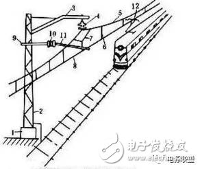
The contact net is a high-voltage transmission line that is erected in the shape of a zigzag in the electrified railway and is taken by the pantograph. The contact network is the main structure of the railway electrification project. It is a special form of transmission line that is erected along the railway line and supplies power to the electric locomotive. It consists of contact suspension, support device, positioning device, pillar and foundation.