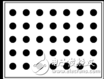
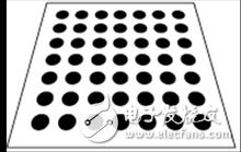
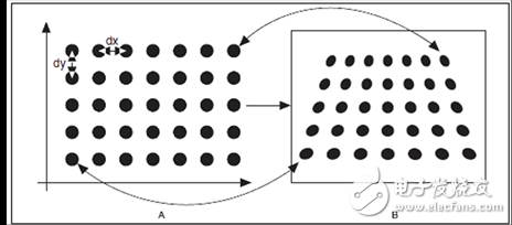
Abstract : A method of machine vision calibration is described. Based on the small hole imaging camera model, a number of photos were taken using a flat panel for verification. Using geometric coordinate transformation, combined with homogeneous graphics, the camera's internal and external parameters are calculated considering the lens distortion of the camera. Such methods can be widely used for calibration of cameras used in machine vision. Machine vision mainly refers to the use of a camera to automatically obtain images through CCD or CMOS, and then analyze the images, such analysis can be automatic or manual judgment. With the increasing degree of industrial automation today, more and more machine vision is used in industrial production. It can be said that machine vision has developed rapidly in the past two decades. In the use of machine vision, measurements of size or shape are applied in large quantities, just like common measurement tools, which require pixel calibration before use. The pixel calibration of machine vision refers to the comparison between the picture taken by the camera and the real object to obtain the mathematical relationship between the two, and the picture can be corrected by this relationship, thereby eliminating the occurrence of various errors when the picture is taken. Deformation. Pixel verification is an essential part of the vision system used to measure machine vision, especially for high precision measurements. A picture taken by a camera stores all the information in units of pixels. Pixel verification uses a mathematical method to restore a pixel-based image to our usual measurement units, such as millimeters, feet, and so on. As with normal photography, when we know the hardware parameters such as focal length, CCD or CMOS size, we can calculate the proportional relationship. For example, one pixel corresponds to 1 mm, and that 100 pixels corresponds to 100 mm. However, when the camera takes an image, the ratio of the shooting angle is not completely linear due to the slight deformation of the CCD or CMOS, and the distortion of the lens. This time you need to use pixel check, which through complex calculations, the system produces the entire image in a true world mapping relationship. The following common deformation pictures need to be restored by pixel verification: Deformation picture due to shooting distance Deformed picture due to shooting angle Deformed picture due to CCD or CMOS and lens Deformed picture due to the height of the object in three dimensions/front/back/up and down 1) Make a rectangular calibration plate with dots, where the color of the plate is white and the color of the dots is black. 2) Using the camera to take a calibration version, you can get the deformed image 3) Use mathematical methods to get the mapping between the two images By comparing the picture with the real object, the horizontal difference dx and the vertical difference dy of the center point of the dot. The mathematical formula is expressed as follows: Common distortions are classified into radiation distortion and tangential distortion. For radiation distortion, the following formula can be used to correct [2]: Tangent distortion is caused by CCD or CMOS mounting variations and can be represented as follows: For tangential distortion, it can be corrected using the following formula: Based on the above theoretical knowledge, experiments can be carried out with visual software. Here we chose to use the open source software OpenCV for verification. Use this function to take at least 2 images for different angles of the checkerboard. If you want to get accurate results, it is recommended to take multiple pictures from different angles for calibration. Before calibration: During calibration: After calibration: For improved accuracy, you can also use a dot checksum board, but this requires modifying some of the OpenCV code. Use the checkpoint verification board: Checking: After verification: By considering the common distortion, the influence of the camera internal parameters and the camera's external parameters, the coordinate system model is established, which can give the machine vision pixel calibration more accurately. For different check panels and multi-dimensional check panels, further experiments are needed to confirm their accuracy. References [2] Bradski, G. and Kaehler, A. (2008) Learning OpenCV: Computer Vision with the OpenCV Library. O'Reilly, Sebastopol. Here you can find the related products in Recordable Sound module, we are professional manufacturer of Greeting Card Sound Module, Recordable Sound Module, Recordable Musical Module. We focused on international export product development, production and sales. We have improved quality control processes of Recordable sound module to ensure each export qualified product. Greeting Cards Sound Module, Recordable Sound Module, Recordable Musical Module AST Industry Co.,LTD , https://www.astsoundchip.com
1) The mathematical mapping method based on physical characteristics is as follows: 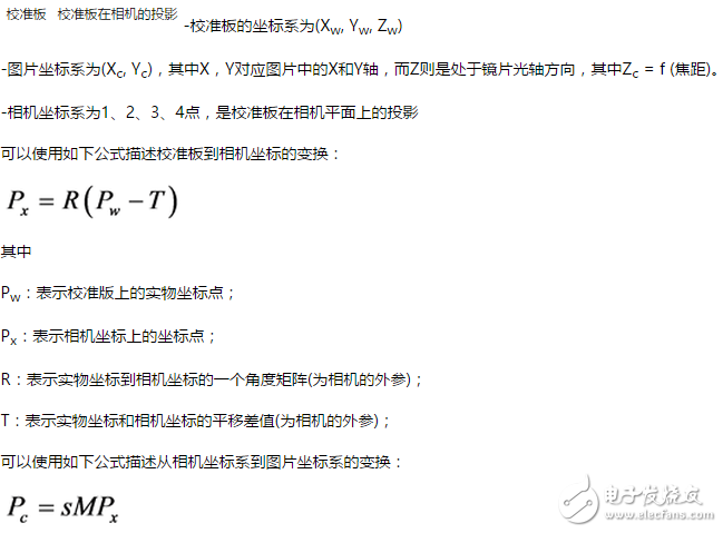
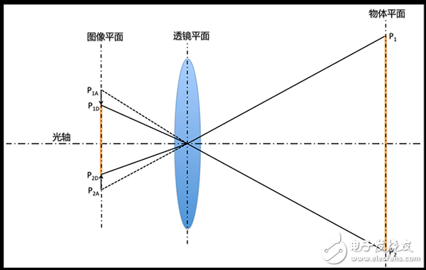
Radiation distortion is caused by the deviation of the lens and can be expressed as follows:
Where: P1A is a projection of the point P1 on the image plane without distortion;
P1D: projection of the point P1 on the image plane in the case of distortion;
P2A: the projection of the point P2 on the image plane in the case of no distortion;
P2D: Projection of point P2 on the image plane in the case of distortion. 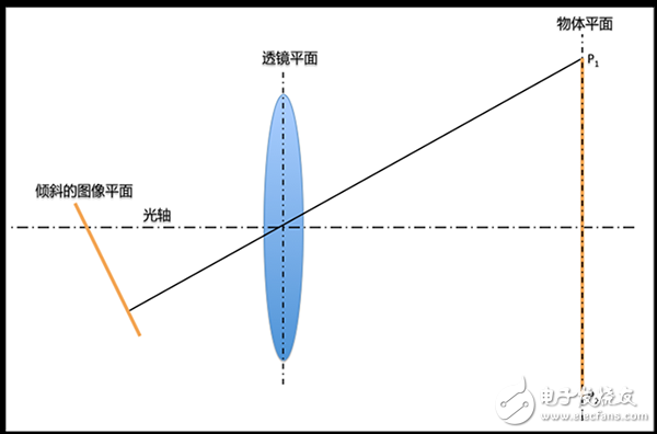
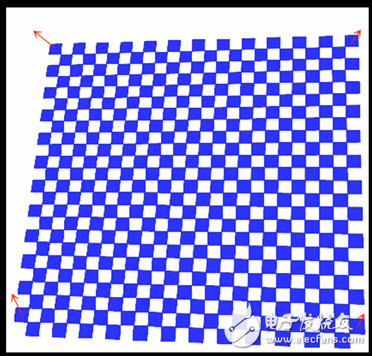
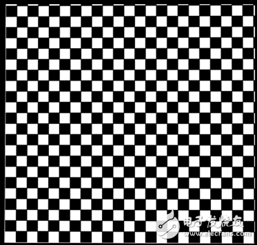
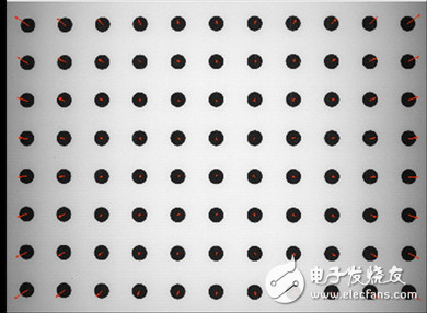
Camera verification based on OpenCV:
OpenCV uses a checkerboard as a checkerboard:
If you want to get the camera's internal parameters, external parameters and distortion, you can use the verification function provided by OpenCV:
Void cvCalibrateCamera2(
CvMat* object_pointsCvMat* image_pointsint* point_countsCvSizeimage_sizeCvMat* intrinsic_matrixCvMat* distorTIon_coeffsCvMat* rotaTIon_vectors CvMat* translaTIon_vectors = NULL, int flags = 0
); 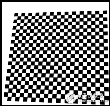
Before verification: 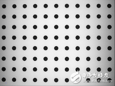
[1] Sonka, M., Havac, V. and Boyle, R. (2011) Image Processing, Analysis, and Machine Vision. 4th EdiTIon, Cengage Learning, New York.
If you want to know more about the products in Recordable sound module, please click the product details to view parameters, models, pictures, prices and other information about Greeting Card Sound Module, Recordable Sound Module, Recordable Musical Module.
Whatever you are a group or individual, we will do our best to provide you with accurate and comprehensive message about Recordable sound module!