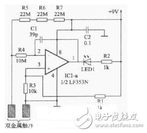
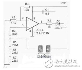
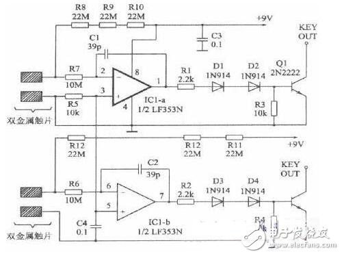
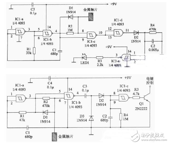
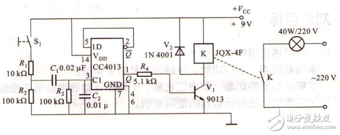
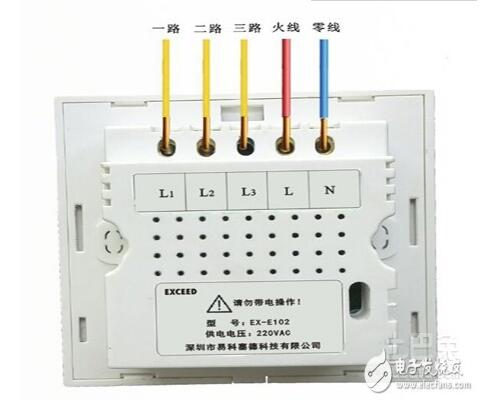
Touch switches are an emerging product of technological advancement. He generally refers to a wall switch designed by the principle of touch sensor chip, which is a replacement product of the traditional mechanical button type wall switch. The touch switch which can realize more intelligent and more convenient operation has the advantage that the traditional switch is incomparable, and is a very popular decorative switch of the current household products. First, the resistance bridge touch switch The resistance bridge touch switch shown in Figure 1 uses the LM339. The LM339 is a four-voltage comparator (with four identical voltage comparators inside). This circuit uses only one of them, and the operating voltage range is as wide as 2— 32V. When the bimetal piece that is close to but not in contact is touched by hand, the second pin of the LM339 outputs a low level signal, so that the LED 1 of the light emitting diode is turned on. The difference between the resistor bridge touch switch shown in Figure 2 and Figure 1 is mainly the use of the operational amplifier LF353N instead of the voltage comparator. The LF353N is a dual operational amplifier, and only one of these circuits is used. When the bimetal is touched, the first pin of the LF353N outputs a low level signal, so that the LED 1 is turned on. The difference between FIG. 3 and FIG. 2 is that when the bimetal is touched, the first leg of the LF353N outputs a high level voltage, so that the LED 1 is turned on. Figure 4 is a key control circuit designed for amateur radio CW telegraph applications. Second, single metal touch switch The circuit shown in Figure 5 uses only one piece of touch metal. The circuit uses two four-two inputs (there are four identical internals with two inputs) Schmitt trigger 4093 (such as CD4093, TC4093). and many more). Generally, the third pin of the output of IC2-a is at a low level, and the LED 1 of the LED cannot be illuminated. When the metal piece is touched, the output terminal becomes a high level, so that the LED 1 is turned on. Figure 6 is similar to Figure 5, using fewer components and directly outputting the key control voltage. Third, the circuit principle of the touch button switch circuit based on CD4013 integrated circuit The working principle of the touch button switch circuit is pressed by the switch S1. The 9V power supply is charged by the R1 and R2 voltages to charge the capacitors C1 and C2 to provide a trigger pulse to the 3 pin of the CD4013 to make the CD4013's 1 pin get a high level and R4 to make the V1 saturated. Turn on, the relay pulls the light bulb to illuminate. Press the 3 pin of switch S1CD4013 again to get a trigger pulse to get a low level of pin 1 of CD4013. R4 turns off the V1 off relay and the lamp is extinguished. Repeated operation of the light bulbs in turn. There is a power supply and a power supply inside the touch switch, so don't make a mistake, the other is the same as the ordinary light wiring. One is connected to the fire wire, one is connected to the bulb, and the other end of the bulb is connected to zero. The live and neutral wiring posts of the alternating current are not positive or negative. As long as the two wires are not in contact, which hole is connected. It is best not to operate with electricity. If it is not energized, be sure to insulate the tools such as screwdrivers. In the operation, be careful not to touch another thread. The rectifier bridge composed of four diodes and the unidirectional thyristor VS constitute the main loop of the switch, and the control loop of the switch is mainly composed of the integrated circuit M668. The 220V pulsating DC output of the rectifier bridge is limited by R1, VD5 is regulated, and the C1 filter output is about 6V DC, which is sent to the 8-pin and 1-pin of the IC for IC power. The human body touch signal is sent to the touch sensing input terminal SEN of the IC via M, R7 and R8, that is, pin 2, and the pin 7 of the IC, that is, the trigger signal output terminal TR, outputs a series of trigger pulse signals, which are added to the gate of the VS via C3. Turn the VS turn-on light on. Touch M again. When the 7th pin stops outputting the trigger pulse signal, when the AC power crosses zero, the lamp will be off. The external oscillating resistor and the oscillating capacitor of the R4 and C2 ICs trigger the pulse oscillator. The synchronization signal of the IC is divided by R2 and R3 and input via 5 pins. The 4 pin of the IC is the function selection end. Now it is connected to VCC high level. The touch function is: touch M once, the light is on; touch again, the light is off. If the 4 pin is changed to the low level of the vss terminal, it is the 4-speed dimmer switch, and the brightness is changed once by touching once. The above switch installation experts gave a detailed explanation. In fact, the installation of the touch switch is difficult, and simple and simple. Here, Xiao Bian advises everyone that if you have a little understanding of the circuit electrical knowledge, or have a certain foundation for the switch installation, you can follow the above instructions to install the touch switch. However, if you do not understand the circuit and switch installation, go to the relevant store to find a professional switch installation master, in order to ensure safety and ensure the quality of the switch installation. Sports can't be abandoned more freely
And can form a triangular stable support with the ear, even if running and riding, vigorous fitness is still close to the ears, wildly shake off.
Description of connection OK Noise Cancelling Earbuds,Bluetooth Earphone Price,Half In-Ear Wireless Headset,Wireless Bluetooth Earphones Guangzhou HangDeng Tech Co. Ltd , https://www.hangdengtech.com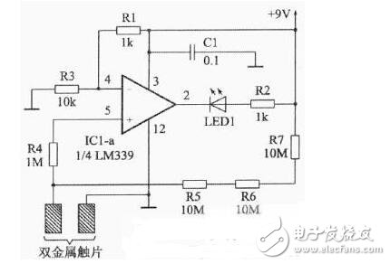
Close ergonomic design, close to the ear, even wearing for a long time can also enjoy comfortable experience.
music doesn't wait
After the first successful pairing, the boot automatically back up, no unnecessary operation
When the earphone is turned on, it can be automatically reconnected.
Note: the first pairing should be done manually in the bluetooth Settings of the device only Ensure that the bluetooth function of the device is turned on normally