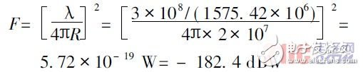
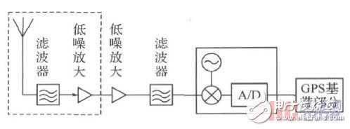
According to the positioning principle of the GPS receiver and the sensitivity of the GPS receiver to analyze the performance of the receiver, it is found that the sensitivity is closely related to the front-end circuit and the base. Accordingly, filters and low-noise amplifiers are designed for the antenna front-end circuit of GPS, and other requirements of the circuit are required. Consider Cyclone devices including processors and a large number of logic gate circuits, and design GPS reception by configuring embedded soft-core processing. machine. The GPS system is capable of providing continuous and high-precision ship positions in maritime transportation, and plays an extremely important role in ensuring the safety and economy of the ship and ensuring navigation on the planned route. High-sensitivity GPS receivers require receivers to be able to locate and track in scenarios where satellite signals are weak. Sensitivity indicators for GPS receiving systems include tracking sensitivity, capture sensitivity, and initial startup sensitivity. At present, the GPS receiver can basically achieve tracking sensitivity below -160 dBm, and the sensitivity and capture sensitivity of the initial startup can reach -142dBm and -148dBm, respectively. The sensitivity of a GPS receiver is mainly determined by two aspects: One is the gain and noise performance of the receiver front-end signal path, and the other is the algorithm performance of the baseband part. The receiver front end determines the signal-to-noise ratio when the received signal reaches the baseband portion. The baseband algorithm determines the minimum signal-to-noise ratio required for the demodulation, acquisition, and tracking processes. The navigation carrier signal of the GPS satellite is the L-band (L 1 : 19cm; L2 : 24 cm) radio wave signal. The current GPS working satellite uses the L-band three navigation signals, respectively L 1 , L2 , L3 , and their carrier frequencies are respectively For: 1 575 42, 1 227 60 and 1 381. 05 MHz GPS signals are transmitted from a satellite at a distance of 20 000 km from the ground to the ground, and their free space attenuation in the L 1 band ( f L1 = 1 575. 42 MHz) is: According to the GPS interface control document (interface cONt ro ldocument, ICD), the minimum signal strength of the GPS system L 1 band C/A code is -160 dBW, and the GPS system designs the effective flux of the C/A code signal transmission in this band. The effect ive isot ro pic radiated pow er (EIRP) is P=478. 63 W( 26. 8 dBW) [4]. If the atmospheric attenuation is 2.0 dBW, then the GPS system L 1 band C/A code signal arrives. The strength of the ground is: In fact, due to the satellite elevation angle of the GPS receiver and the obstruction of the obstacle, the intensity of the L 1 band C/A signal reaching the receiver may be lower than -160 dBW. The circuit structure of the GPS receiver is shown in Figure 1. Figure 1 GPS receiver circuit structure Increasing the sensitivity of the GPS receiver is most important to reduce the minimum detectable signal power at the receiving front end and reduce the total noise figure of the receiver so that the signal-to-noise ratio can be improved from the noise background. The first stage filter of the antenna part is pre-filtered to prevent interference from affecting low-noise amplification, but it also increases the noise figure of the previous stage. Therefore, a small insertion loss filter is used, such as Kalman filter. Technology can greatly improve receiver accuracy. 11.1V Lipo Battery Battery,Rechargeable Battery With Charger,11.1V 8Ah Lithium Battery,Rechargeable Battery Charger,Power Battery Packs Langrui Energy (Shenzhen) Co.,Ltd , https://www.langruibattery.com