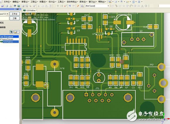
This article explains the difference between PCB positive and negative, PCB positive negative output, manufacturing process difference and difference, and PCB negative use, what are the benefits, etc., you can find the answer here. PCB positives and negatives are the opposite of the manufacturing process. The effect of the PCB positive film: wherever the line is drawn, the copper of the printed board is retained, and the place where no line is drawn is removed. The signal layer such as the top layer and the bottom layer is the positive film. The effect of the PCB negative film: Wherever the line is drawn, the copper of the printed board is removed, and the place where no line is drawn is preserved. Internal Planes layer (internal power/ground layer) (internal power layer) for arranging power and ground. The traces or other objects placed on these levels are copper-free areas, ie the working layer is negative. Negative film: Generally speaking, we are talking about the tenTIng process, and the liquid used is acid etching. Negative film is because after the film is made, the desired line or copper surface is transparent, and the unnecessary part is black or brown. After exposure by the line process, the transparent part is chemically affected by the light of the dry film resist. Hardening, the subsequent development process will wash away the dry film without hardening, so only the dry film is etched away in the etching process to wash away part of the copper foil (the black or brown part of the film), while leaving the dry film is not Washing out the line that belongs to us (the transparent part of the film), after leaving the film, we leave the line we need. In this process, the film should be covered by the hole, and the exposure requirements and requirements for the film are slightly higher. Some, but the process of its manufacture is fast. Positive film: Generally speaking, we are talking about the pattern process, and the liquid used is alkaline etching. If the positive film is viewed from the negative film, the desired line or copper surface is black or brown, and the part is transparent. Similarly, after the line process exposure, the transparent part is chemically affected by the light of the dry film resist. Hardening, the next development process will wash away the dry film without hardening, followed by the process of tin-lead plating, plating the tin-lead on the copper surface washed by the dry film of the previous process (development), and then removing the film. Action (removal of dry film hardened by light), and in the next process etching, bite off the copper foil without tin-lead protection (the transparent part of the film) with alkaline syrup, and the rest is the line we want (negative film) Black or brown part). Negative film is used to reduce the file size and reduce the amount of calculation. The place where there is copper is not displayed, and the place where there is no copper is displayed. This can significantly reduce the amount of data and computer display burden in the formation power layer. However, the current computer configuration is no longer a problem for this amount of work, I feel that it is not recommended to use negative film, it is easy to make mistakes. The pad is not designed to have a short circuit or something. If the power supply is convenient, there are many methods. The positive film can also be easily divided by other methods. It is not necessary to use a negative film. Magnetic Buzzer Self-drive Type
The magnetic buzzers (Self-drive Type) offer optimal
sound and performance for all types of audible alert and identification. Our
magnetic Buzzer solutions are offered with various mounting options. We also
provide you with a washable version for your preferred soldering method. Our magnetic buzzers, also known
as indicators, are designed with an internal drive circuit for easy application
integration. During operation, current is driven through a voice coil to
produce a magnetic field. When a voltage is applied, the coil generates a
magnetic field and then allows the diaphragm to vibrate and produce sound. This
buzzer type has a low operating voltage ranging from 1.5 – 12V+. Our magnetic
buzzers are desirable for applications requiring a lower sound pressure level
(SPL) and frequency.
Passive Buzzer,Dc Magnetic Buzzer,Electro Magnetic Buzzer,Magnetic Buzzer Self Drive Type Jiangsu Huawha Electronices Co.,Ltd , https://www.hnbuzzer.com