Saving energy and protecting the environment have become a necessary condition for sustainable development of mankind. People's attention is turning to the use and development of renewable energy. Among them, solar power has become a hot spot in recent years. However, its low power generation efficiency has become an important factor restricting development. At present, Maximum Power Tracking (MPPT) technology is one of the effective ways to improve power generation efficiency. In recent years, with the continuous advancement of electronic technology and silicon materials research, the development and utilization of wind energy and solar energy have been promoted, and the market prospect is quite broad. Under this premise, a new generation of wind and light complementary integrated power system with intelligence, modularity and integration has been developed. CBD Vape Pod Shenzhen Xcool Vapor Technology Co.,Ltd , http://www.xcoolvapor.com
1 wind and solar hybrid power generation system
Wind and light complementary power supply systems mainly consist of wind turbines, solar panels, battery packs and power supply integrated control cabinets. The design concept is to use the solar panel and wind turbine dual power generation system to charge the battery pack (48V), and then convert the DC power into AC 220V/50Hz AC power, which becomes our common AC power supply. The charging mode of the battery pack determines the length of its service life, but the suddenness of wind energy and the time of solar energy are destined that the power generation system cannot output reliable and stable DC power. If the battery pack is directly charged without treatment, the battery pack is greatly shortened. Life expectancy, and can not effectively use wind and solar energy. Therefore, the control system based on the digital power following technology of ATMEGA8 single-chip microcomputer is introduced in the charging process, which not only greatly improves the stability of the power generation system, but also improves the reliability of the power supply system.
2 charging system
Taking the fan as an example, the main circuit of the charging system adopts the DC conversion module PH600S28048 of a company of Nissan, the DC input voltage: 200~400V, and the output voltage: 43~6lV remotely adjustable. The fan is a three-phase line voltage 220V output, and the charging voltage range of the battery pack is 46~57V. The constant current and power of the charging are followed by ATMEGA8. The schematic diagram of the system composition is shown in Figure 1. 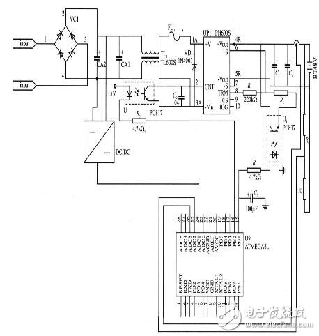
Figure 1 System schematic
3 system working principle
ATMEGA8 is a high performance, low power 8-bit AVR? The microprocessor has 130 instructions for advanced RISC architecture; 32 8-bit general purpose working registers can operate fully statically; performance up to 16 MIPS at 16 MHz; hardware multiplier with only two clock cycles; non-volatile program And data memory; 8K bytes of in-system programmable Flash; optional Boot code with independent lock bits to achieve true simultaneous reading and writing of in-system programming through the on-chip Boot program.
The charging current is converted into a standard signal of 0~5V by the Hall current sensor, converted into a digital signal by A/D and sent to the CPU for processing, and passes through the PBl pin. The PWM output controls the output of the diaphragm PC817 to control the output voltage of the charger, thereby achieving constant current through simple digital PI regulation. However, an important prerequisite for constant current operation of the charger is that the input energy must have sufficient power. However, the natural wind energy, the solar energy, and the suddenness of the solar current make it difficult to achieve constant current charging. Especially for wind energy, if the wind speed is particularly large and the charger still outputs a constant current (the load does not change), the fan will be damaged. If the wind speed is not enough, the charger will not work properly, and sometimes it will be turned off and then turned on. This phenomenon is caused by the charging module PH600S working normally with an input voltage range of DC 200~400V. In order to overcome this situation, digital power following technology has been added to adjust the load size based on the A/D conversion number of the fan input voltage of 300V. The output current is adjusted by the digital PI to achieve normal operation of the charger.
4 software design ideas
The AVR MCU is an enhanced RISC (Reduced Instruction Set CPU) RISC instruction set high-speed 8-bit MCU developed by ATMEL in 1997. AVR's single-chip microcomputer can be widely used in computer external equipment, industrial real-time control, instrumentation, communication equipment, household appliances and other fields. In 1997, Mr. A and Mr. V from Atmel's Norwegian Design Center used Atmel's new Flash technology to jointly develop a RISC reduced instruction set high-speed 8-bit microcontroller, referred to as AVR.
The program is written using the assembly language specific to the AVR microcontroller. The schematic diagram of the monitoring program and input control module program flow is shown in Figure 2. 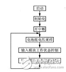
Figure 2 monitoring main program flow chart
All program code consists of analog digital acquisition, median filtering, digital comparison, PWM output and so on. The key is that the digital comparison constitutes a simple PI adjustment and the current loop is nested within the voltage loop.
The program flow is as follows: Take the current loop as an example: The output current of the hardware charger consisting of PH600S series modules is linearly adjusted by 0~5V signal. The current given signal (0~5V) is output by the ATMEGA8 single-chip PBl port. The pulse width modulation waveform is generated by RC filtering. Set the T/Cl control register TCCRlA of the M8 microcontroller to the value 83H, and the TCCRlB control register to 05H to define the PB1 port to output the 10-bit fast PWM waveform. The value of the T/C1 count register TCNTI (TCNT1H:TCNT1H) is changed from 0000 to 01FH. The pulse output duty cycle (output voltage) is generated by comparing the set value of the comparison control register OClA with the count value of the TCNT1 register; the content of OClA is variably set by 0000-0lFFH to determine that the output voltage is linearly adjustable from 0 to 5V. The OClA value is given by the voltage loop after the analog PI adjustment operation, so that the mutual nesting of the voltage loop and the current loop constitutes a constant follow of the power, thereby improving the efficiency of the wind and light complementary power generation.
5 Conclusion
The principle of power follow-up of the solar charging circuit and the fan is the same, except that the input voltage of the solar panel is low and the change is relatively slow. The PH30048-48 module has been used as the main circuit. Using the ATMEGA8 single-chip microcomputer for control, the wind-solar hybrid power generation system made by the DC conversion module of a company of Nissan has been operating in the garrison of Huaying Island in Shanghai for more than 2 years. It is very stable and has been well received by the military leaders.