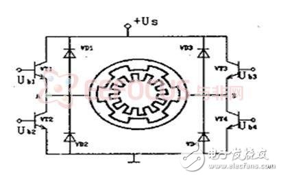
1 Introduction 1.1 High-pressure advection pump control status The high-pressure advection pump is a kind of equipment that uses a motor to drive a plunger pump to make the liquid output at a steady flow and pressure. As a power source of the analytical instrument, it is widely used in petroleum, chemical, food, pharmaceutical, coal, environmental protection and other industrial fields. The main technical requirements are: pressure range 0~42MPa, flow rate range 0.001~9.999mL flow error less than 0.5%, from the technical parameters, such a small flow, high precision, high pressure flow meter is more difficult to manufacture. The advection pump, also known as a constant flow pump, requires a constant flow rate. The setting of the flow of the advection pump is essentially to change the rotational speed of the motor, so how the constant current effect depends mainly on the stability of the motor speed. At present, most of the domestically produced constant current pumps are driven by stepper motors. This kind of pump has low cost and convenient debugging, but the Achilles heel is that there is a large pulsation at low flow rate, and it is difficult to ensure the constant current effect. This is because the stepper motor operates in a certain beat and phase sequence. In order to solve this problem, we can learn from foreign instruments and replace the stepping motor with a DC motor, so that the performance of the constant current pump is greatly improved [1]. DC motors have good linear speed regulation characteristics, simple control performance, high efficiency, excellent dynamic characteristics, and are especially suitable for systems that require speed regulation. Most of the motor controllers on the market today use single-chip microcomputers and DSPs. However, the data processing capability of the traditional single-chip microcomputer is limited. For the system with complex feedback control, the large amount of data to be processed, high real-time and high precision requirements often fail to meet the design requirements. In recent years, various high-speed SOC microcontrollers have appeared, and their performance has been greatly improved, and the price is much lower than DSP. With more and more related software and development tools, the functions are getting stronger and stronger, but the price is decreasing. Now more and more manufacturers are adopting SOC microcontrollers to improve product cost performance [2]. 1.2 Main content of this article The system uses PWM technology to adjust the speed of the DC motor in a closed loop to precisely control the flow of the advection pump. The system has very high precision requirements for high-pressure advection pumps, and the flow accuracy requirements are less than 0.5%. Such high precision requires a high-performance controller to collect and adjust the DC motor speed. The PIC32MX460F512L can meet the requirements. It samples the DC motor speed, analyzes and processes the PWM signal with appropriate duty cycle to the motor, thus precisely controlling the DC motor speed. . In order to improve the stability of the system, the motor drive uses the motor-specific drive chip LMD18200. The system provides triple protection of pressure, current and thermal alarms to prevent damage to the advection pump. The pressure and current are sampled by the A/D module provided by the PIC32MX460F512L with an accuracy of up to 10 bits [8]. In order to facilitate human-computer interaction and debugging system, the system provides stable and reliable communication functions, and the communication part is isolated by optocoupler to provide RS232 communication. 2 related technologies and principles 2.1 DC motor control method Among all kinds of electromechanical systems, DC motor speed control systems have been widely used in various fields of industry and aerospace because of the good starting, braking and speed regulation performance of DC motors. With the advancement of semiconductor technology, the rapid development of power electronics technology has improved the transmission technology of DC motors. The three basic speed control methods commonly used in the past are: (1) changing the total resistance of the armature circuit; (2) changing the electricity. The power supply voltage of the pivot; (3) change the excitation magnetic flux, develop into a thyristor phase-controlled rectifier motor voltage regulation system, and full-wave uncontrolled rectification - PWM rolling DC motor voltage regulation speed control system [3]. DC motor pulse width modulation (PWM) DC speed regulation has the characteristics of high speed regulation accuracy, fast response speed, wide speed regulation range and low loss, which makes it the main speed regulation method for DC motor applications. 2.2 PWM DC speed regulation principle PWM control is a technique of modulating the width of a pulse by effectively mediating the width of a series of pulses to obtain the desired waveform. The speed control circuit based on PWM control "rolls" the flow voltage into a series of pulses, and the required output voltage is obtained by changing the duty cycle of the pulse. In the speed control system of the PWM drive control, the rotation speed of the motor is controlled by changing the ratio of the on-time of the motor armature voltage to the energization period (ie, the duty ratio). A pulse width modulation method is used to modulate a constant DC power supply voltage into a pulse voltage sequence of variable frequency width, thereby changing the average output voltage to adjust the motor speed. It can be seen that under the DC voltage, when the modulation pulse frequency is constant, the pulse width is linear with the duty cycle. Under the action of a pulse, the power supply can be controlled in real time by turning the power on and off at a fixed frequency. The speed increases when the motor is energized; the speed decreases when the motor is de-energized. When the motor is directly connected to the power supply (ie, the duty ratio is 100%), the motor speed is Vm, and the duty ratio is D=t/T, then the average speed of the motor is (2-1) Where: Ve - average speed; Vm - full speed (ie speed when directly energized); D = t / T - duty ratio (0-100%). It can be seen from equation (2-1) that Vm is the speed (full speed) when the DC motor is directly energized. It is only related to the characteristics of the motor itself. When the motor is fixed, Vm is a fixed value. By changing the duty cycle D=t/T, different average speeds can be obtained, so that the motor speed can be controlled in real time [4]. Strictly speaking, the average speed and the duty cycle D are not strictly linear. In a general application, the approximation can be regarded as a linear relationship. 2.3 H-bridge motor drive principle Figure 2-1 H-bridge PWM driver The main circuit (power amplifier) ​​structure of a common PWM drive system is: H type and T type. Here, the H-shaped structure is taken as an example to illustrate the working principle of the PWM bipolar drive circuit. The H-bridge PWM drive is shown in Figure 2-1. In the figure, VD1, VD2, VD3, and VD4 are freewheeling diodes to protect the VT1, VT2, VT3, and VT4 transistors. Ub1=Ub4=-Ub2=-Ub3. When Ub1=Ub4 is positive, VT1 and VT4 are turned on, VT2 and VT3 are turned off, and UAB=Us. Carton Closing Staples,Packaging Industrial Staple,Copper Coated Staple,Moistureproof Packing Nails Zhejiang Best Nail Industrial Co., Ltd. , https://www.beststaple.com