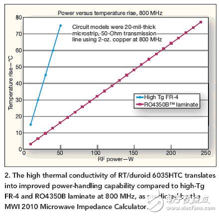
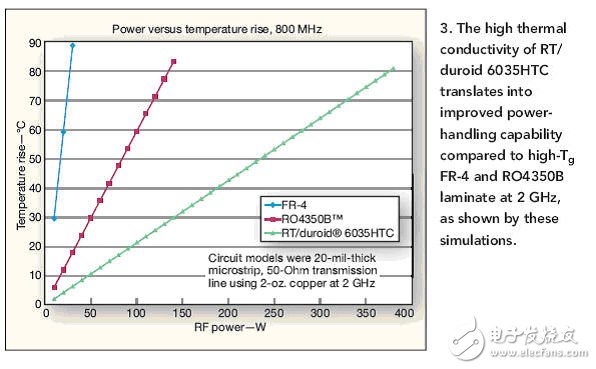
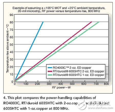
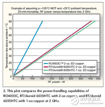
Proper thermal management in RF/microwave designs begins with careful selection of electronic materials, and printed circuit boards (PCBs) are the most important of these materials. In high-power, high-frequency circuits such as power amplifiers, heat may accumulate around active devices in the amplifier. To prevent damage to device junctions, nearby circuit components, or even PCB materials, the system must properly conduct heat away from the active device and pass through the device package, circuit ground, heat sink, device chassis, and ambient air safety Distributed. The choice of PCB material has a great influence on the overall thermal management of high-power RF/microwave designs. The power handling capability of a circuit material is related to its ability to control temperature rise, which is a function of applied power and dissipated power. For most electronic components, elevated operating temperatures will shorten their operating life and often reduce their electrical performance. Whether the ambient temperature is high or the temperature of the circuit and its components is increased due to high-power operation, the result will be high-temperature damage and performance degradation. Depending on the amount of power that the circuit must dissipate, keeping the circuit at a lower temperature generally ensures higher reliability. What happens to the PCB at high temperatures? Like most materials, the PCB will expand and contract with temperature changes - when the temperature rises, the PCB will expand in three axial directions (length, width, and thickness). This degree of expansion due to temperature changes can be characterized by the coefficient of thermal expansion (CTE) of the PCB material. Because PCBs are typically formed from copper-clad (used to form transmission lines and ground planes) dielectrics, the linear CTE of the material in the x and y directions is usually designed to match the copper's CTE (about 17 ppm/°C). In this way, these materials expand and contract together with changes in temperature, thereby minimizing the stress at the junction of the two materials. The CTE of the z-axis (thickness) of the dielectric material is generally designed to be a lower value in order to minimize dimensional changes with temperature and maintain the integrity of plated through-holes (PTH). The PTH is a ground and multilayer circuit board interconnect that provides the required path from the top layer to the bottom layer of the board. In addition to mechanical changes, temperature also affects the electrical performance of the PCB. For example, the relative permittivity of a PCB laminate is a function of temperature, defined by the thermal coefficient of permittivity. This parameter describes the change in dielectric constant (the unit is usually ppm/°C). Since the impedance of the high-frequency transmission line depends not only on the thickness of the substrate material but also on its dielectric constant, the z-axis CTE and the variation of the dielectric constant as a function of temperature significantly affect the microstrip fabricated on this material. And the impedance of the ribbon transmission line. Of course, microwave circuits rely on closely matched impedances between components and circuit junctions to minimize reflections that can cause signal loss and phase distortion. In a power amplifier circuit, an impedance matching circuit is used to achieve a conversion from a typical low impedance of a power transistor to a typical 50 Ω characteristic impedance of an RF/microwave circuit or system. Changes in the impedance of the transmission line caused by the temperature effect of the high power signal may change the frequency response of the high frequency amplifier. Therefore, these effects should be minimized by careful selection of the PCB laminate. There are many other parameters that are useful when selecting PCB materials that help to minimize heat generation at high power levels and high frequencies. At a certain temperature point, some materials will change its state. This temperature is one of the parameters—it is called the liquid glass transition temperature or the glass transition temperature (abbreviated as Tg). For example, it can indicate the temperature at which a large change will occur in the CTE characteristics of a material (Figure 1). Since the CTE of a material can undergo considerable changes, the mechanical and electrical properties of the material can become unstable when the operating temperature exceeds Tg. Therefore, in addition to the short-term processing (such as during the reflow process, the material requirements are high Outside temperature, the operating temperature should always be kept below this temperature. Figure 1: The coefficient of thermal expansion (CTE) of a PCB material changes drastically above the glass transition temperature Tg of the material and becomes mechanically and electrically unstable. Another key temperature-related parameter is the maximum operating temperature (MOT) of the PCB. MOT is a rating of a single PCB structure definition produced by a Underwriters Laboratories (UL) for a particular circuit fabrication site using a specific PCB material. The MOT is the maximum temperature at which the PCB can operate normally over any length of time without significantly degrading critical circuit performance attributes. If the circuit is operated at a temperature higher than the MOT for a long time, the reliability risk will be worth considering. The MOT rating means that the PCB provides a safe high temperature indication, although it does not include the impact of high input power levels on the PCB. The thermal conductivity of the PCB material can be used as a relative indicator of the thermal efficiency of the laminate. This parameter essentially describes the thermal conductivity of the PCB material, which is measured in Watts per Watt of material per watt of temperature. Similar to conductivity and the flow of electrons in a material, thermal conductivity is used to predict the rate of energy loss as heat passes through a given material. The reciprocal of thermal conductivity is the rate of thermal resistance, or the ability of the material to block heat flow. Track thermal conductivity Thermal conductivity depends on various properties of the material, such as its molecular structure. For example, glass is a poor thermal conductor with a very low thermal conductivity of 1.1 W/(mK). On the other hand, the resistance of copper to heat flow is very low, with a very high thermal conductivity of 401 W/(mK). Since the thermal conductivity of PCB dielectric materials is particularly low (the thermal conductivity of high Tg FR-4 circuit materials is generally around 0.24 W/(mK)), the heat can be easily conducted on the power PCB leads (these wires are usually It is made of copper with extremely low thermal resistance. However, PCB materials with higher thermal conductivity are selected to allow the circuit to operate at higher power levels. The following table compares some typical PCB laminates (including Rogers' relatively newer product RT/duroid 6035HTC laminates). As shown in the table, RT/duroid 6035HTC materials have much higher thermal conductivity than FR-4 and even several low loss high frequency laminates. This material consists of a ceramic filled PTFE composite dielectric and a standard or reverse treated electrolytic (ED) copper foil. Due to its high thermal conductivity, the material is widely used in hundreds of watt power microwave amplifiers for efficient thermal management. On the z-axis, it has a relative permittivity of 3.50 at 10 GHz and its tolerance on the entire circuit board remains within ±0.05, maintaining the impedance of the transmission line. The CTEs of the x and y axes are 19 ppm/°C, which closely matches the CTE of copper. Of course, in circuit design, proper thermal management is not simply the selection of circuit laminates with the best thermal properties. There are many other factors that can affect the temperature of a circuit that operates at a given power level and frequency. For example, the circuit material is characterized by a dissipation factor, which is the loss caused by the dielectric material. There is also loss through conductive transmission lines (such as microstrip lines or stripline circuits), and the higher the insertion loss, the more heat the transmission line will produce at higher power levels. The roughness of copper conductors on the PCB can lead to increased insertion loss, especially at higher frequencies. In addition, the choice of the dielectric constant of the PCB material will determine the size and density of the RF/microwave circuit because the size of the microwave transmission line structure depends on the signal wavelength to be processed. When the relative permittivity is large, the size of the transmission line required to reach a given impedance will be small, and the power handling capability of the PCB will be limited by the width of the wire and the insertion loss and ground plane spacing. For example, for an amplifier circuit, selecting a PCB material with a small relative dielectric constant can make the transmission line wider for a given impedance, thereby improving heat flow. The use of PCB materials with relatively high relative permittivity will lead to finer transmission line sizes and tighter pitch circuits, which may lead to hot spots in high power circuits. In addition, the choice of materials with low dissipation factor helps to minimize the insertion loss of the transmission line and optimize the gain of the amplifier circuit. Using the free MWI 2010 Microwave Impedance Calculator software, we simulated the characteristics of several different PCB laminates when used at high power levels and used MOT as the key parameter to determine the maximum RF power that each material can actually handle. The MOT for each material is assumed to be +105°C. In each calculation use case, the ambient temperature used is +25°C (room temperature). At the same time, the temperature rise above the ambient temperature is predicted for different power levels. Two ounces of copper were used as a conductive laminate on each material, and the same 20 mil thick, 50 Ω microstrip line test circuit was fabricated. Comparing the high Tg FR-4 laminate with Rogers' RO4350B laminate, it can be seen that at 800 MHz, the difference in power handling capability is very significant for comparable temperature rise (Figure 2). At a RF power level of about 40W, the temperature rise of the FR-4 relative to the environment is about +75°C; and the RF power of the RO4350B laminate is approximately 250W at about +77°C relative to the ambient temperature rise. Figure 2: Predictions from the MWI 2010 Microwave Impedance Calculator show that the RT/duroid 6035HTC's high thermal conductivity translates into higher power handling capabilities than the 800MHz high Tg FR-4 and RO4350B laminates. Increase RT/duroid 6035HTC laminates to 2GHz higher frequency MWI 2010 simulations, assuming that the circuit and material (2oz copper) conditions are the same as in the 800MHz simulation, when the temperature rises to ambient temperature close to +90°C, FR The -4 actually exhibits a lower power handling capability (approximately 25 W); while the RO4350B operating at 2 GHz shows a temperature rise of approximately +85°C for approximately 150 W of RF power (Figure 3). The RT/duroid 6035HTC is designed specifically for high power usage. After these MWI 2010 simulations show that when operating at 2GHz frequency and 350W RF power, the relative temperature rise only exceeds +80°C. These simulations not only made us more aware of the expected power of RT/duroid 6035HTC laminates at high power levels, but also realized the frequency dependence of the power handling capabilities of the other two materials. Figure 3: These simulation results show that the RT/duroid 6035HTC's high thermal conductivity translates into higher power handling capabilities than the 2GHz high Tg FR-4 and RO4350B laminates. When the above three materials are tested with the same test circuit, but each circuit receives a test signal of the same frequency and power level, the high Tg FR-4 exhibits the highest temperature rise - up to +109°C (+229°F) Or the relative ambient temperature is increased by +84°C; the temperature rise of RO4350B laminate is +56°C, and it rises from +25°C to +82°C (+180°F); RT/duroid 6035HTC is under the same test conditions and is relatively environmentally friendly. The temperature rise is only +36°C (from +25°C to +62°C). We tested the Rogers RO4003C laminate and RT/duroid 6035HTC laminates with 1 oz ED copper and 2 oz ED copper under the same conditions for all other tests. This test revealed a very interesting result of the copper surface influence. When the test frequency is 800MHz (Figure 4), the temperature rise of all three laminates to ambient temperature reaches +80°C, the RO4003C laminate using 2 ounces of ED copper requires approximately 280W of power and uses 2 ounces of ED copper. The power required for RT/duroid 6035HTC is about 700W, and the power required for RT/duroid 6035HTC with 1oz copper is close to 800W. When the test frequency is 2GHz (Figure 5) and the temperature rise is the same, the power handling capability of the RO4003C drops to about 140W. The power handling capability of the RT/duroid 6035HTC with 2oz copper is about 380W, while the RT with 1 oz copper is used. /duroid 6035HTC's power handling capability exceeds 400W. The reason for using 1 oz. copper RT/duroid 6035HTC over the same dielectric with a thicker cladding is that the former has a smoother copper surface (and thus a smaller insertion loss). Figure 4: This figure compares the power handling capabilities of the RO4003C with 2oz copper, the RT/duroid 6035HTC, and the RT/duroid 6035HTC with 1oz copper operating at 800MHz. Figure 5: This figure compares the power handling capabilities of the RO4003C, RT/duroid 6035HTC with 2oz copper and the RT/duroid 6035HTC with 1oz copper operating at 2GHz. These tests described above show that all PCB materials experience a temperature rise when dealing with high RF power levels. However, different materials and even different copper layers can affect the power handling capability of the circuit. If conservative MOT parameters are considered in order to ensure a long service life for PCB laminates and high frequency designs, low material loss, high thermal conductivity, and stable mechanical temperature characteristics should be taken into account when selecting materials.
Laptop power adapter charger for Dell:
Our service:
Stable output and high charging efficiency.
Elegant outlook design as original one, touch smoothly and comfortable.
Original charger is good, but as a replacement, our product has more reasonable price when your original charger is broken.
And, the market of the replacement adapters becomes bigger and bigger. People would rather buy a copy one then the original because of the price.
But at the same time, people worry about that they will buy something defective. So the problem comes, how to buy a good quality one with a good price?
As a professional power adapter manufacturer, we have excellent R&D team, skilled staffs and responsible after-sale service. All your benefits can be under protected after you buy products for our company.
Our certificates :ISO9001:2008 & ISO14001:2004 , CCC , CE , FCC , ROHS.
All our products has 1 year warranty. In other words, if you get the dad products which are not damaged physically from us in one year, we will replace you the new one or the whole bulk order.
Mini Charger For Dell,Big Connector Adapter,45W Power Adapter,Dell Computer Adapter Shenzhen Waweis Technology Co., Ltd. , https://www.waweisasdapter.com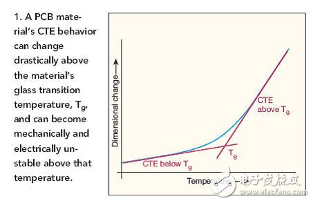
Laptop Model
Adapter Output
Latitude E5400 E5410 E5500 E5510
19.5v 4.62a, 7450
Studio XPS 16 (1645)1640 1645 1647
19.5v 4.62a, 7450
Studio XPS M1645 M1647
19.5v 4.62a, 7450
XPS 14 15 17 L501x L502x L702x L702x
19.5v 4.62a, 7450
Inspiron 1464 1564 1764
19.5v 4.62a, 7450
Inspiron 1525 1440 1526
19.5v 3.34a, 7450
Precision M4600 M6600
19.5v 6.7a, 7450
Inspiron N5050 N4010 N5110
19.5v 3.34a, 7450
Inspiron 14Z-N411Z 13Z N311Z
19.5v 4.62a, 7450
Inspiron 1545
19.5v 3.34a, 7450
Latitude E5420 E5530 E5430 E6420
19.5v 4.62a, 7450
Inspiron 1440 1525 1526 1545 1750
19.5v 3.34a, Octagon tip
Inspiron 1300 B120 B130
19v 3.16a/3.42, 5525
Inspiron 1525 1526 1545
19.5v 3.34a, 7450
Studio 1440 1440n 1440z 14z 14zn
19.5v 3.34a, 7450
Latitude E4300 E4310
19.5v 4.62a, 7450
Inspiron 13Z 13ZD 13ZR M301 M301z M301ZD M301ZR N301
19.5v 3.34a, 7450
Inspiron N301Z N301ZD N301ZR
19.5v 3.34a, 7450
Studio 1535 1536 1555 1557 1558
19.5v 4.62a, 7450
Latitude E5420 E5520 E6430 E6530 E6420 E6520
19.5v 4.62a, 7450
Inspiron Mini 10 10v 1010 1010n 1010v 1011 1011n 1011v
19v 1.58a, 5517
Inspiron 14V 14VR M4010 N4020 N4030
19.5v 4.62a, 7450
Inspiron N4110 N5110 N7110 M5010
19.5v 3.34a, 7450
630M 640M E1405
19.5v 4.62a, 7450
Inspiron 15-3521 17-3721
19.5v 3.34a, 7450
Latitude 120L
19.5v 3.34a, 7450
Vostro 1710 1710n 1720 1720n
19.5v 4.62a, 7450
Vostro 1500 1700 Inspiron 1520 1521 1720
19.5v 4.62a, 7450
Vostro 1400 1420 PP26L
19.5v 3.34a, 7450
Latitude D410
19.5v 3.34a, 7450
Inspiron 1120, 1121, M101
19.5v 3.34a, 7450
Inspiron Mini 1012 1018
19v 1.58a, 5517