More convenient and faster charging method is what we have been pursuing. In recent years, a new type of charging technology has begun to appear in our field of vision, it is wireless charging. Wireless charging is derived from wireless energy transmission technology. Low-power wireless charging is often performed by electromagnetic induction. High-power wireless charging often uses a resonant type to transmit energy to a powered device by a power supply device (charger). The device uses the received energy. Charge the battery and use it for its own operation. Copper Tube Terminals Without Checking Hole Our company specializes in the production and sales of all kinds of terminals, copper terminals, nose wire ears, cold pressed terminals, copper joints, but also according to customer requirements for customization and production, our raw materials are produced and sold by ourselves, we have their own raw materials processing plant, high purity T2 copper, quality and quantity, come to me to order it! Copper Tube Terminals Without Checking Hole,Cable Lugs Insulating Crimp Terminal,Cable Connector Tinned Copper Ring Terminal,Tubular Cable Lugs Crimp Terminal Taixing Longyi Terminals Co.,Ltd. , https://www.longyiterminals.com
Since the magnetic energy is transmitted between the charger and the electric device, the wires are not connected between the two, so that the charger and the electric device can be exposed without conductive contacts.
This article describes a simple and practical wireless energy transfer charger solution that wirelessly transmits electrical energy to a light bulb (battery) through a coil. The wireless energy transfer charger is composed of two parts, an energy sending unit and an energy receiving unit, and can charge the bulb (battery) within a range of 5 cm.
Power circuit 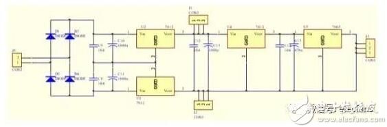
The 24V and 5V power supplies are used to supply the FET, NE555, respectively. After the transformer is used, the 7812 and 7912 regulator source modules are used to generate 24V points and then the 7805 power supply is used to generate 5V. And be sure to pay attention to the two power supplies.
Signal generation circuit 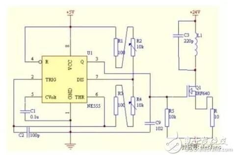
The NE555 is used to form a signal generator with an oscillation frequency of about 500 kHz, which provides an excitation signal for the power amplifier circuit. Adjusting the varistor size of 555 can change the frequency and duty cycle of the output square wave within a certain range, and adjust to obtain the required frequency.
Receiver charging control circuit design 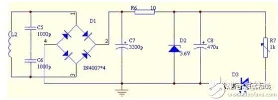
After the electric energy is received by the coil, the high-frequency AC voltage is full-wave rectified by the IN4007 rectifier tube, the capacitance of 2200uf is filtered, and then the 3.3V Zener diode is used to wake up the voltage regulator, and the output DC power provides a relatively stable working voltage for the bulb (battery).
Amplifier Drive Circuit The resonant power amplifier consists of an LC parallel resonant tank and a switching transistor IRF640. The power amplifier driving circuit is mainly used for amplifying the oscillation signal generated by the previous stage oscillation circuit, thereby sending a higher oscillation signal to the lower stage high frequency power generating circuit.
LC resonant circuit design The RF output end of the energy transmitting unit uses a transmitting coil (inductor) and a capacitor to form a resonant circuit. In order to increase the energy receiving unit to obtain a larger voltage, it is able to work at a longer distance, and the energy receiving unit adopts a parallel resonant circuit.
When the resonant frequency of the frequency selective loop of the power amplifier is the same as the excitation signal frequency, the power amplifier resonates, and the voltage and current in the coil reach a maximum value, thereby generating the largest alternating electromagnetic field. When the receiving end coil is close to the transmitting coil, an induced voltage is generated in the receiving coil, and when the resonant frequency of the receiving coil circuit is the same as the transmitting frequency, resonance occurs, and the voltage reaches a maximum value. Therefore, when both the transmitting coil loop and the receiving coil loop are in a resonant state, the best energy transmission effect is obtained. The coil delivers higher energy efficiency and a larger transmission pitch.
After receiving the charging control circuit, the high-frequency AC voltage is fully rectified by the IN4007 rectifier tube, the 2200uf capacitor is filtered, and then the 3.3V Zener diode is used to wake up the regulator, and the output DC power is provided for the bulb (battery). Stable operating voltage.
Editor's Note The editor believes that this wireless pass-through charger solution has the following points to note:
(1) In the case of the transmission distance and the coil parameters have been determined, the transmitting end must have a higher frequency, and the transmitting coil operates in a resonant state to increase the transmission efficiency.
(2) The method of increasing the distance may be to increase the voltage of the transmitting circuit of the device.
(3) This design uses IN4007 rectifier to rectify, the average pressure drop of the tube is 0.8V. The conduction loss is large and is not suitable for use in a receiving circuit. If a Schottky diode is used, the tube loss can be greatly reduced, and the power utilization rate is higher.
(4) The diameter of the copper wire, the diameter of the coil, the number of turns and the winding method not only determine the inductance value of the coil, but also affect its transmission efficiency.