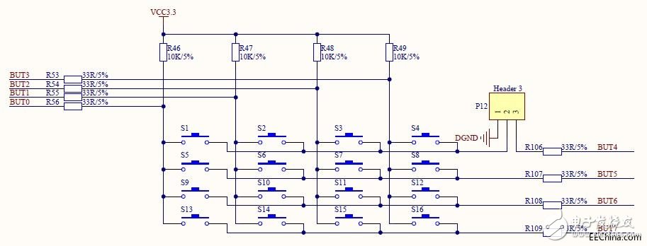
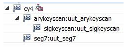
Keyboard sub-coded keyboard and non-encoded keyboard. The recognition of the closed key on the keyboard is realized by a dedicated hardware encoder, and a key code or key value is generated as a coded keyboard, such as a computer keyboard. The software programming to identify the non-coded keyboard. In general embedded applications, the most used is a non-encoded keyboard, but also used to encode the keyboard. Non-encoded keyboard is divided into independent keyboard and determinant (also known as matrix) keyboard. The so-called free-standing keyboard, that is, a GPIO port of an embedded CPU (or MCU) corresponds to a key input, and the state of the input value is the key value. The matrix keyboard is used to collect the key GPIO is multiplexed, generally divided into rows and columns to collect, for example, 4 * 4 matrix keyboard only requires the ranks of the four keys on it, the matrix keyboard control is more complex than the independent keyboard More than this experiment did not involve, so its principle is not described in detail. Independent buttons generally have 2 sets of pins. Although we often see 4 pins on the market, they are normally turned on in pairs. The 2 pins are disconnected when the button is not pressed. , is turned on when the button is pressed. Based on this principle, we generally ground one pin of the button, and the other pin is pulled up to VCC and also connected to the GPIO. In this way, when the button is not pressed, the connection state of the GPIO is pulled up to VCC, and the value of the key is 1. When the button is pressed, the GPIO is pulled up to VCC, but the other pin that is turned on at the same time Pulled to the ground, so its key is actually 0. Our SF-CY4 development board has a set of 4*4 matrix keyboards. When short-circuited by PIN 1-2 of P12, S1/S2/S3/S4 can be used as independent keys. One end is grounded, and the other end is connected to the FPGA I/O port while being pulled up. When the level of the I/O port is high (1), the button is not pressed. When the level of the I/O port is low (0), the button is pressed. This is how we use it in section 8.4. In this example, we are no longer limited to the application of independent buttons such as low, here we will use all 16 buttons to achieve our real matrix button function. To do a matrix button, you must first make sure that the PIN2-3 of your SF-CY4 development board socket P12 is shorted with a jumper cap. The matrix button schematic is shown in Figure 8.85. Figure 8.85 Matrix button schematic Following the schematic above, let's look at how the matrix key's key is obtained. Usually, we divide this matrix key into two signals, namely column signals (including BUT0/BUT1/BUT2/BUT3) and row signals (BUT4/BUT5/BUT6/BUT7). The column signal serves as the input signal to the FPGA and the row signal serves as the output signal of the FPGA. If the output signal of the FPGA is high level, no matter whether a button is pressed, the level of the column signal input to the FPGA is always at a high level, which cannot achieve any matrix key value acquisition; if the FPGA output line When the signal is low, there is no button press, then the column signal will remain high (because there is a pull-up), when the key is pressed, because the button will short the row and column signals, then the level of the column signal will Due to the line signal being pulled low, in this way, we can achieve the key value detection. However, there may be doubts that if the 4 line signals are pulled down at the same time, then any 4X4 button will be pressed and all the column signals will be pulled down. This can only determine if any button has been pressed. It is not known if the button is pressed. Indeed, the solution is very simple. We can only pull down one of the four line signals at the same time, then it will position the button state to a specific line, so that it can be positioned directly to this line of buttons as an independent button. Which button in the middle was pressed. In terms of implementation, we will let the 4 line signal cycle pull down, and at the same time there is only one line signal output is low, which is what we call the "keyboard scan" principle. This example implements the acquisition of matrix key values ​​(that is, which of the 16 keys is judged to have been pressed), and then displays the key values ​​(the display value is 0-F in hexadecimal) through the nixie tube. The lowest digit of the digital tube displays the last time. The key value, the upper 3 digits shows the previous value, that is, each time the key is pressed, the key value of the nixie tube is shifted to the right by one. As shown in Figure 8.86, detecting 16 button values ​​with 8 signals is a bit difficult, but we have already mentioned in the previous section. From the functional point of view, we first perform button debounce on four column signals as input, and then sequentially output different line signal values ​​to find the values ​​of special column signals when the keys are pressed, so that the key values ​​can be acquired. Send to digital display. Figure 8.86 Matrix Button Scan Example Functional Block Diagram The engineering structure is shown in Figure 8.87. cy4.v is the top-level module. It does logic and only defines and connects signal interfaces. The anykeyscan.v module achieves the line signal output; sigkeyscan.v achieves the column signal debouncing and key value acquisition; seg7.v is the digital tube driver module. Figure 8.87 Matrix Button Scanning Example Module Hierarchy Stainless Steel Round Bar,304 Stainless Steel Round Bar,Stainless Steel Flat Bar,Stainless Steel Threaded Rod ShenZhen Haofa Metal Precision Parts Technology Co., Ltd. , https://www.haofametals.com