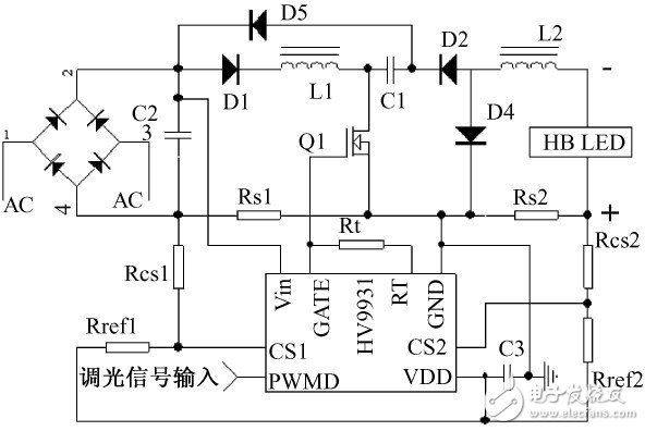
High-power LED lights have many advantages such as energy saving and high efficiency, and have great development prospects. Their driving and dimming have been the hotspots of research in recent years. Therefore, this article has conducted in-depth research on led street lights, and designed the driving circuit and intelligence of LED street lights according to their characteristics The dimming circuit constitutes the LED street lamp system. The driving circuit is a Buck-Boost-Buck circuit controlled by HV9931, which is directly driven by the city power supply to achieve constant current drive and has PFC function; the dimming method adopts PWM dimming, and uses TLS2561 as the light intensity sensor, which is controlled by PIC16C62 to generate PWM Optical signal control HV9931 realizes intelligent dimming. The experimental results show that the circuit has high conversion efficiency, high power factor, small THD of input current, white LED street lights are pure in color and energy-saving, and have great market prospects and value for further research. 1 Introduction LED is considered to be the fourth generation of green light source. It is a solid cold light source. It has many advantages such as high efficiency, long life, safety and environmental protection, small size, fast response and so on. It is currently used in urban landscape equipment, traffic signals and commercial advertising. widely used. In recent years, with the continuous development of manufacturing technology, the performance of high-power high-brightness LEDs has continued to improve, and prices have continued to decline. At present, the same obvious effect has been achieved. The power consumption of LEDs is about 1/10 of incandescent lamps and 1/2 of fluorescent lamps [ 2]. All these make it begin to be used in general lighting, and have great development prospects. There is a trend to replace traditional light sources such as incandescent lamps and fluorescent lamps. The application of LED lamps at the World Expo can be said to represent this direction. LED dimming can save energy. The driving and dimming of high-brightness white LEDs have been the focus of research in recent years. This article has conducted some research in this area and designed an LED street light driver with power factor correction and an intelligent dimming system. . 2 LED characteristics, driving requirements and dimming method The theoretical light effect of LED is 300lm / W. The current laboratory level is 260lm / W, and the market level is above 120lm / W. The general turn-on voltage of high-brightness LEDs is about 3.0 ~ 4.3V, but the core is still a PN junction, and its volt-ampere characteristics are the same as ordinary diodes. When the voltage applied to the LED is less than its turn-on voltage, almost no current flows through the LED. However, when the LED is turned on, its forward current changes exponentially with the forward voltage, and a small voltage fluctuation will cause a large current change. In the conduction zone, the voltage rises from 80% to 100% of the rated value, and the current rises from 0% to 100% of its rated value. Figure 1 Relationship between LED relative luminous flux and forward current Figure 1 shows the relationship between the LED's relative luminous flux and its forward current IF. It can be seen from the figure that the luminous flux of the LED is proportional to its forward current, so it is possible to control the brightness of the LED by controlling the forward current of the LED. If the LED is driven by a constant voltage source, a small voltage change will cause a large current change, so the constant voltage drive is only suitable for occasions where low power is not required. In high-demand applications and high-power applications, LEDs are driven by constant current. The research shows that the luminous brightness of the LED decreases with the working time. After the brightness decreases, the light effect decreases with the increase of the current. The brightness of the LED has a saturation relationship with the drive current. After the LED current reaches 70% ~ 80% of its rated current, a large proportion of the current is converted into heat energy, so the driving current of the LED should be 70% ~ 80% of the rated current of the operating current. In constant voltage drive or PWM dimming, the maximum current should not exceed 3 times the minimum current, otherwise the inrush current will greatly reduce the life of the LED [8]. At present, the power of a single LED in the market is not large, most of which is below 10W. The actual use of lighting is to form a LED array after a plurality of LEDs are connected in a certain square or in series and parallel. It can also be drawn from Figure 1 that changing the LED current can change the LED brightness. There are two ways to change the current, and there are two ways to adjust the corresponding LED dimming. One is to continuously adjust the size of the current in the LED to change the brightness of the LED. This method is called analog dimming. The current through the LED is continuous; the other is to change the time and turn off the current flowing through the LED. The ratio of the time to change the brightness of the LED. The current is constant when the LED flows. The current flowing through the LED is zero when it is turned off. This method is called PWM dimming. It is a frequency that is not noticeable by the human eye. Fast switching LED, the switching frequency should not be less than 100Hz. When the average current flowing through the two dimming modes is the same, the effect is the same. Since the LED emits the purest white light at a certain current of a certain size, as the current deviates from this value, there will be a color shift. In addition, the response time of the LED is only a few nanoseconds to tens of nanoseconds, which is very suitable for the occasion of frequent switching, so the LED dimming is good by PWM dimming. In addition, this method is also conducive to LED heat dissipation. 3 LED drive circuit 3. 1 LED drive circuit classification The power supply from the LED can be divided into AC / DC type and DC / DC type, and the LED requires DC power supply. When AC power is supplied, the AC must be converted into DC before driving the LED, so we only need to study the DC / DC type. can. The driving method of DC / DC type LED can be divided into resistance current limiting type, linear regulated power supply type, capacitive charge pump circuit and inductive switching conversion circuit. Resistor current limiting connects resistors and LEDs in series, and can control the accuracy of this method by dividing the current of the resistor and driving the LED lamp. At the same time, a large amount of electric power is wasted on the resistor, and it is only used in low-voltage occasions that do not require much. The accuracy of the linear regulated power supply is higher than that of the resistor current limiting type, but it also has the problem of low efficiency, and not much is used in practice. In practice, the charge pump circuit and the inductive switching conversion circuit are much used. The charge pump circuit uses the cumulative effect of the capacitor on the charge to store electrical energy, applies the capacitor as an energy coupling element, and switches by controlling the high-frequency switch of the power electronic device, allowing the capacitor to store energy during a part of the clock cycle, and the remaining time of the clock cycle The internal capacitor releases energy. In this way, different output voltages are obtained through different connection methods when the capacitor is charged and discharged. Inductive switching converter circuit, also known as switching power supply, changes the output voltage by controlling the time relationship between power switch tube on and off. Inductance and capacitance are generally used as filter components to stabilize the output. In comparison, the charge pump type uses fewer components, has a lower cost, and has a smaller size, but it uses more switching elements and has a relatively lower efficiency. The output voltage is within the range of 1/3 to 3 times the input voltage, and the output power is small. , So it is mostly used in low power occasions; and the switching elements of switching power supply are relatively few, high efficiency, can achieve a wide range of voltage output, and the output voltage is continuously adjustable, the output power is large, so the scope of application is wider, especially in It is the first choice in high-power situations. There are many topologies of switching power supplies. Boost circuits, Buck-Boost and Buck circuits are much used in LED drive circuits. 3. 2 HV9931-based LED street lamp drive circuit design There are already some LED-driven chips. LED street lamps are relatively large in power, and are powered by AC power. National regulations require that power factor correction devices be used when the power reaches a certain value. In addition, the designed LED street lamps must have a dimming function to save energy. Based on the above considerations, the HV9931 function driving chip of Supertex is selected here. HV9931 is an 8-pin PWM integrated controller with the following functions and features: (1) Constant output current, suitable for LED constant current drive; (2) Allow a wide range of 8 ~ 450V DC input voltage , And has a large step-down ratio, so you can use a commercial power supply to drive an LED lamp without a transformer; (3) With power factor correction function, you can obtain unit power factor and low input current harmonics, meet national regulations, environmental protection; (4) With PWM dimming and analog dimming functions, dimming control can be conveniently achieved when driving LEDs, which meets the energy saving requirements; (5) The oscillator has two working modes: fixed frequency and fixed off time. Fig. 2 LED street lamp driving circuit based on HV9931 The driving circuit is shown in Figure 2, which is a switching power supply driving method. The main circuit is a single-stage single-switch non-isolated constant current output Buck-Boost-Buck circuit. Buck-Boost circuit composed of L1, C1, D1, D5 and Q1 is an input stage, working in discontinuous conduction mode; Buck circuit composed of C1, Q1, D2, D4 and L2 is an output stage, working in continuous conduction mode under. The two stages share a power switch Q1, and the capacitor C1 is equivalent to the load for the input stage and the DC power supply for the output stage. The step-down ratio of the system is the product of the two-stage step-down ratio, so that the mains power supply can achieve a lower voltage output without a transformer. When the switch Q1 is turned on, the input-stage Buck-Boos current path: rectified voltage → D1 → L1 → Q1 → Rs1, the current in L1 increases linearly, and the output stage Buck circuit current path is: C1 → Q1 → Rs2 → LED → L2, C1 provides energy; when Q1 is off, the input stage current path: L1 → C1 → D5 → D1, the energy in L1 is transferred to C1, due to the existence of D1, the L1 current cannot be reversed After the current of L1 drops to 0, the current is intermittent; the current path of the output stage: L2 → D4 → LED. Due to the different parameter settings, the current in L2 will not only become 0, and the fluctuation is relatively small. The circuit works in peak current mode, the oscillator makes GATE output high level, and Q1 is turned on; CS1 and CS2 terminals are the inverting input terminals of two voltage comparators inside HV9931, and the two comparators are in the same direction. The input terminal is grounded inside the chip. The circuit detects the input current and output current at the same time through the CS1 and CS2 terminals. CS1 is the input current signal detection terminal and CS2 is the output current signal detection terminal. As long as one of the two terminals has a lower voltage than ground , GATE terminal outputs low level, and Q1 turns off. VDD is the reference voltage output pin of the chip. Rs1, Rcs1 and Rref1 can program the maximum peak current in L1, and Rs2, Rcs2 and Rref2 can program the output current. In the cycle of alternating current, the duty cycle and switching frequency can be considered unchanged, so the peak envelope of the input current is a sine wave, and the average current is a sine wave, which can be corrected by real power factor. C2 is the input capacitor, which is used as a high-frequency bypass. If a large capacitor is used, the circuit will lose the power factor correction function. RT corresponds to the internal oscillator, there are two kinds of connection methods, respectively set constant operating frequency and constant off time, the figure uses a constant off time connection. The PWMD pin is a digital dimming signal input pin. When the pin is at a high level, the circuit works normally. When the pin is at a low level, the GATE pin always outputs a low level, the switch Q1 is off, and the drive circuit does not work.
Bluetooth Earbuds /Tws Earbuds /Sport Bluetooth Earbuds
Product Description
Items an be used simultaneously, also one of them can be used separately. And can connect two devices simultaneously.
HD Microphone, provides clear and loud sound.
Features:
1, True wireless stereo: realizes movement and wireless control and everyone can share music without wrie
2, Comfortable and convenient: Earplug made of food-grade silica gel material in combinalion with the design to avoid falling off, which makes you comfortable and relieved,also the Earbuds can be Dual or Single use.
Photo as below:
Bluetooth Earbuds Bluetooth Earbuds,Wireless Earbuds,Cordless Earbuds,Wireless Bluetooth Headset Shenzhen Greater Industry Co., Ltd. , https://www.szgreater.net