The fuel cell vehicle uses hydrogen as a fuel, and hydrogen reacts with oxygen in the atmosphere. The chemical energy is converted into electric energy through the electrode, and the electric energy is used as the power to drive the car forward. Fuel cell vehicles have high-tech advantages such as high efficiency, no pollution, zero emissions, and no noise. They represent the future development trend of automotive use of new energy, advanced technology and the pursuit of environmental protection, leading the new trend of the automotive industry revolution. The motor drive system is the heart of the fuel cell vehicle and directly affects the performance of the fuel cell vehicle. The development of digital signal processors (DSPs) has made it possible to apply various advanced control strategies to motor drive systems. Model reference adaptive control in electric vehicles can improve the performance of electric vehicle motor drive systems and accelerate the development of the electric vehicle industry. This article refers to the address: http://
All In One Blackboard,Electronic Blackboard,Blackboard Demo,Smart Blackboard Price,Digital Blackboard For Teaching Jumei Video(Shenzhen)Co.,Ltd , https://www.jmsxdisplay.com
l Fuel cell vehicle and its discrete MRAC motor control system The fuel cell vehicle motor studied in this paper is a 5 kW DC traction motor of model XQ-5-5H. The control of the motor adopts double closed loop speed regulation including current loop and speed loop. The system, its structural block diagram is shown in Figure 1. The dashed box in the figure is implemented by a DSP-based control system. This article focuses on the lack of software. 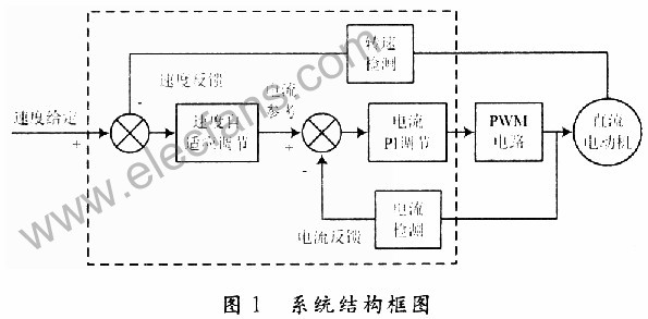
The design of the double closed-loop speed control system is not discussed in detail here, only the design results are given here. The adjustment of the current uses traditional PI mediation, and its transfer function is: 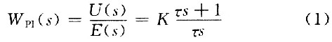
Where: K is the amplification factor of the proportional part of the PI regulator; Ï„ is the integral time constant.
The adaptive mediation method is adopted for the speed adjustment. In order to facilitate the computer implementation, the discrete model reference adaptive control is adopted. The structure diagram is shown in Fig. 2. See the literature for specific instructions. 
2 control system software design
2.1 Hardware System Introduction The hardware system block diagram of the fuel cell vehicle motor drive control system based on FMS320LF2407A is shown in Figure 3. It mainly includes the given signal detection circuit, current detection circuit, speed detection circuit, PWM output circuit and DSP external circuit.  2.2 Main program design The main program includes the initialization program and the loop wait 2 parts. After the system is powered on or reset, the main program runs automatically. It first initializes the system, including hardware initialization, which is based on various hardware such as clock and watchdog module, I/O module, timer, SCI module, ADC module. Timers, control registers, etc. are assigned so that each module works normally, and the program global variables are initialized, mainly including current PI adjustment, speed adaptive control adjustment parameter initialization, and other global variable initialization, and then interrupt and wait.
2.3 PWM interrupt processing program design uses the timer period interrupt flag to start A/D conversion. When T1 underflows, A/D conversion is started. The detected current is processed and connected to the ADCIN00 pin of the analog/digital converter. After the conversion is completed, the interrupt flag bit is set to 1, and the conversion result is read out in the A/D interrupt service routine, and A/D sampling is completed once. After the conversion is completed, the PWM interrupt is applied, and the PWM interrupt completes the main control function. The flow chart is shown in Figure 4. Since the mechanical time constant of the motor control system is much larger than the electrical time constant of the system, the speed loop control period of the system can be larger than the current loop control period. The system performs current sampling and PI adjustment in each PWM cycle, so the current sampling period is the same as the PWM period, real-time control can be realized, and the speed loop control period is selected as one adjustment every 100 PWM periods. . During each current control cycle, the number of pulses counted by the QEP unit is added to the variable speedcount. The variable speedflag is decremented from the initial value of speedstep(100) by one until it is equal to 0. At this time, 100 current control cycles are read (1 speed). The total number of pulses in the control cycle is calculated for speed, and speedcount is cleared, the variable speedflag is assigned an initial value, and the next speed pulse count is started.
2.4 Current PI regulator programming The regulator given by equation (1) is a continuous transfer function. In order to facilitate the realization of the computer, the anti-integration saturation PI regulator is used, and the algorithm is improved as follows: 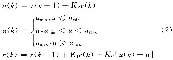
Where: KI = KP / Ï„; KC = KI / KP = T / Ï„, according to the anti-saturation PI regulator algorithm to determine the system flow chart shown in Figure 5. 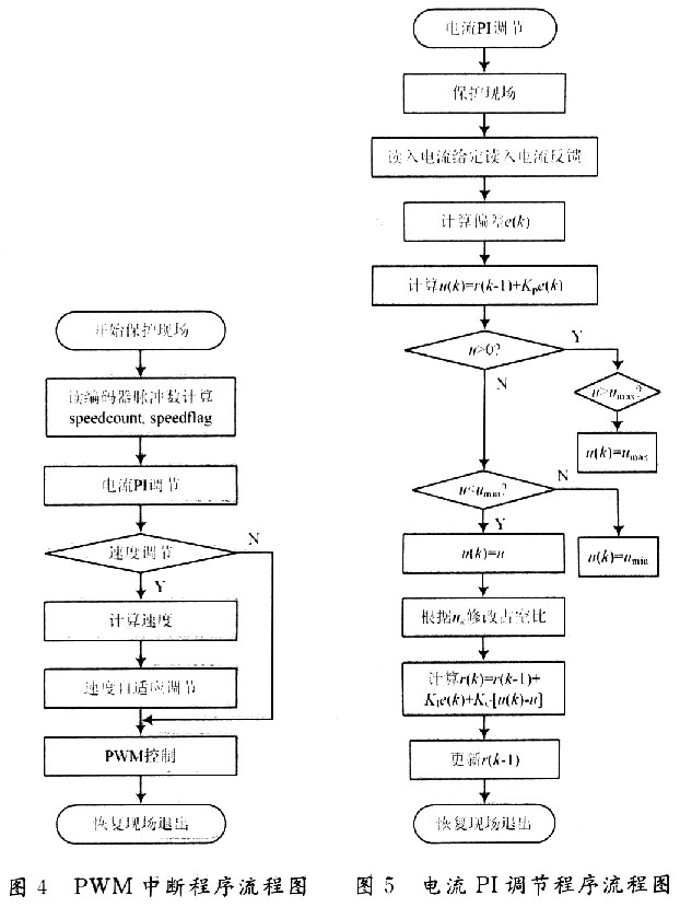
2.5 Speed ​​Adaptive Programming The speed adaptive adjustment algorithm is given in Figure 2. The algorithm is a discrete adaptive algorithm that can be directly used for programming. The discrete model reference adaptation is divided into two parts: the reference model and the controlled object, so we first discuss the implementation of the reference model. For a second-order reference model, the discrete equation can be expressed as: 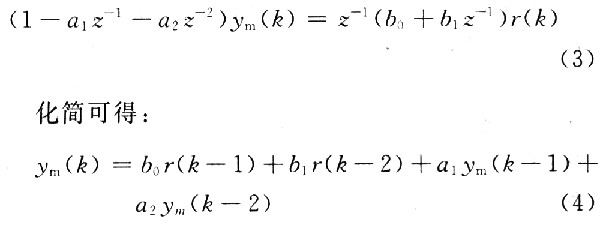
This will give you a reference model output. The speed output y(k) of the controlled object is detected by the speed detection circuit, and the prediction error can be obtained: 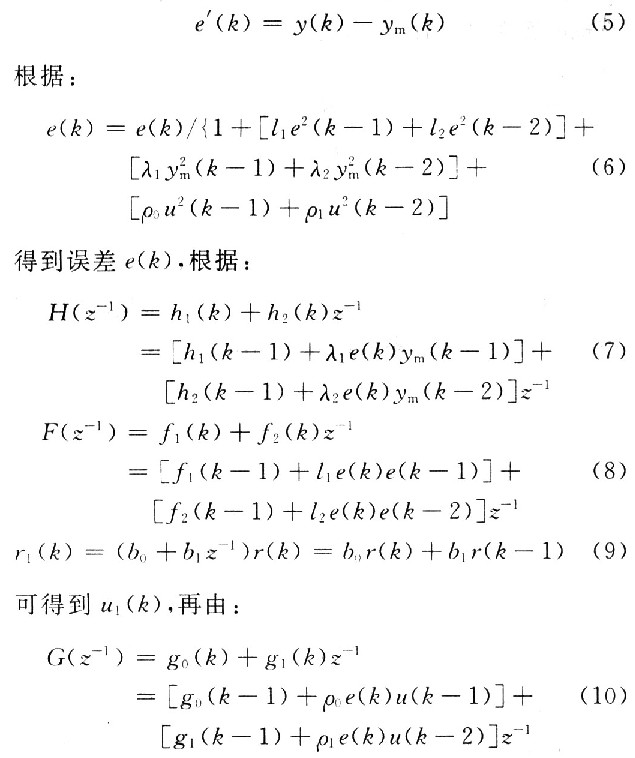
You can get u(k). According to the above analysis, the speed adaptive control program is written, and the flow chart is shown in Fig. 6. 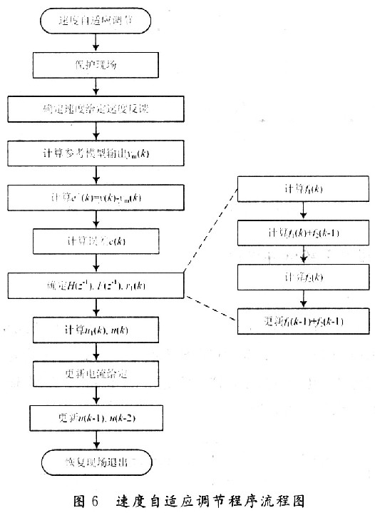
3 Conclusion The application of adaptive control theory in the fuel cell vehicle motor control system has a good effect on improving the driving performance of electric vehicles. This paper discusses the implementation of the discrete model reference adaptive algorithm in the motor DSP control system. It actively explores the application of various advanced control strategies in electric vehicles, and is of great significance for promoting the development of the electric vehicle industry.
Introduction to 85-inch Nano Smart Blackboard Classification


The 85-inch Nano Smart Blackboard is an innovative educational technology product that falls under the category of interactive smart whiteboards. It combines traditional writing surfaces with modern digital interactive capabilities, providing educators and students with a vast interactive platform for teaching, presentation, and collaboration activities.
Dual Writing Surfaces: The 85-inch Nano Smart Blackboard offers dual functionality, supporting both traditional chalk writing and modern digital writing methods such as markers and touch gestures. This versatility allows educators to seamlessly transition between analog and digital teaching methods.
High-Resolution Display: With its expansive 85-inch display screen, the Nano Smart Blackboard provides high-definition visual effects that captivate students' attention in classrooms and lecture halls. The large screen ensures that all learners can clearly see every detail of the content, enhancing understanding and engagement.
Interactive Touch Technology: Interactive touch technology enables educators to directly annotate, mark, and manipulate content on the screen. This interactivity encourages student participation and collaboration, creating a dynamic learning environment.
Multimedia Integration: The Nano Smart Blackboard supports multimedia integration, allowing educators to incorporate videos, images, presentations, and interactive applications into their teaching. This multimedia diversity enriches instructional content to accommodate various learning styles.
User-Friendly Interface: An intuitive user interface allows educators to easily navigate applications, switch between writing modes, and access a variety of tools. This ensures that teachers can focus on delivering impactful lessons without encountering technical obstacles.
Blue Light Protection: Equipped with blue light filtering technology, the Nano Smart Blackboard promotes eye comfort during extended teaching periods. This feature is particularly important for maintaining the health of educators and students.
Collaborative Learning: The large screen encourages collaborative learning, enabling multiple students to interact with the content simultaneously. Group discussions, brainstorming sessions, and interactive quizzes become more engaging and effective.
Remote Learning Capabilities: The Nano Smart Blackboard supports remote learning, allowing educators to conduct virtual lessons and interact with students in real time. This feature enhances accessibility and flexibility in the learning process.
Customizable Tools: Educators can customize a variety of tools on the interface as needed, including pens, markers, shapes, and colors. This flexibility allows for creative content delivery and effective explanations of complex concepts.
Durable Construction: The 85-inch Nano Smart Blackboard is built with sturdy materials to ensure durability and longevity, making it a reliable investment for educational institutions.
The 85-inch Nano Smart Blackboard represents a fusion of tradition and innovation, providing educators with powerful tools to create engaging and interactive learning experiences. Its expansive display, interactive features, and multimedia integration redefine the modern classroom, elevating teaching to new heights.