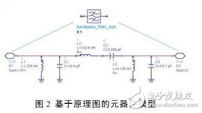
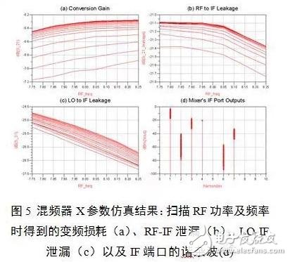
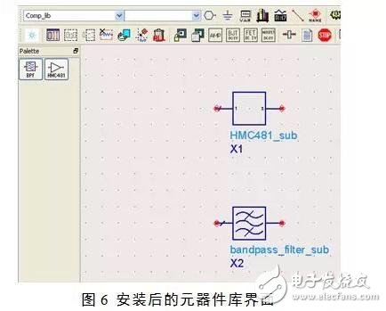
Simulation is the most important and intuitive means of early verification, and it is also an important way to find problems and optimize design during the development process. In this paper, based on different types of devices, a schematic model, a behavioral model and a test model are proposed to establish a radio frequency microwave model library. Among them, the X parameters based on the test results can successfully model nonlinear devices such as amplification modules, detectors, and mixers. The unified RF component model platform will make the existing component parameters electronic, and at the same time facilitate the addition of design circuits or test results of new components, which can ensure the effective development of RF system design. In the design of communication system, in order to ensure system performance and guarantee the development cycle, it is necessary to fully evaluate system performance, verify system algorithm, reasonably distribute subsystem indicators in the system design stage, and use advanced simulation technology to provide technical support for the overall department and improve Each department designs efficiency and promotes collaboration between departments. The construction of the digital prototype development platform is an important attempt based on this demand. Using simulation technology, system modeling and algorithm modeling are carried out in the system indicator allocation stage. The electrical performance of the whole system is obtained through simulation, and the influence of key indicators on system performance is considered. Simulation using simulation technology can consider the interaction between subsystems as early as possible, reasonably distribute system indicators, solve problems through reasonable technical means, and improve system stability. In the development of the digital prototype, the performance of the RF microwave circuit must be considered to maximize the access to the actual operating state of the system. How to consider the performance of components in existing circuits or designs is one of the basic guarantees for the development of digital prototypes. The work of establishing the RF component model library enables the existing component parameters to be electronicized, and at the same time, the design circuit and test results of the new components can be quickly added to ensure the development of the digital prototype design work. At present, RF and microwave designers are still in the stage of designing and debugging according to the indicators. There is no systematic modeling and archiving of the finished products, so there will be some problems: · Lack of a unified design and simulation platform, lacking device model support for system simulation; · Lack of standardized test model library, the use rate of existing circuits is not high, often in different systems, repeat design and debug circuits for similar functional components, resulting in great waste of manpower and material resources; · There is a lack of document management tools. After the organizational structure of personnel changes, existing circuits and modules are difficult to reuse, and the inheritability of existing experience is not high; · There is no suitable model for nonlinear devices to describe. For devices such as amplifiers and mixers, descriptions of broadband and power-related metrics are not possible. In view of these current problems, the RF, microwave and system design software with the highest market share is selected. The ADS of Keysight is used as a design platform to construct the RF component model library to meet the basic circuit unit in the design of the RF system. Demand. For the design and use of RF circuits, the device model, component icons, help and documentation, and version control documents are organically integrated to form a library of RF component models with uniform style and flexible content. The specific composition of the model library is shown in Figure 1: The focus of the library construction is to select the appropriate model to properly characterize the components. Based on the characteristics of RF microwave components, the component model library is divided into three models for modeling. The schematic-based model can directly bring the sub-circuit into the last circuit and system for simulation, but if multiple sub-circuits are added, the system simulation speed will be slower. Both behavioral and test-based models fall into the category of black-box models. The schematic-based model is the design flow for top-down system metrics planning, and the measurement-based model is the bottom-up design process for system performance verification. 3.1 Schematic-based model Some common circuits can directly extract the model of the schematic, and generate sub-circuits, which are directly called in the later circuits. Figure 2 is a very typical sub-circuit structure. By adding the icon of this filter, the corresponding sub-circuit topology can be quickly added to the circuit. 3.2 Behavioral Model Behavioral models are based on the electrical operating characteristics of components, considering components as "black boxes", measuring the electrical characteristics of their ports, and extracting device models, which can be used to describe the operating characteristics of the device. Typically, polynomials are used to fit the operating characteristics of the amplifier. If the gain, noise figure, output power, 1dB compression point, third-order intercept point, etc. of a certain frequency provided by the device manufacturer in the product manual can be added to the existing model, the system automatically fits the working curve of the device. As shown in Figure 3, the input of the device parameters at different frequencies into the amplifier model can obtain the response of the amplifier at different frequencies and powers. 3.3 Measurement-based model Many times, based on intellectual property protection considerations, even the sharing of schematics between colleagues or departments is unlikely. The device or circuit designer can be asked to perform model extraction to provide a black box model of the device. More often, it is very difficult to obtain a schematic or behavioral model of an RF component. This requires that existing devices or external devices must be tested and modeled to create a model library. Model parameter extraction or measurement can be divided into two categories: linear models and nonlinear models. 3.3.1 Linear Model Extraction For linear models, an n-port scatter matrix (S-parameter) can usually be used for the description. The S parameter uses the incident voltage wave and the reflected voltage wave to define the input and output relationships of the network, thereby characterizing the characteristics of the entire network. The S parameter is in the Touchstone file format, also known as the SnP file. SnP files can be generated directly using a vector network analyzer. Most passive components can be characterized using linear models such as filters, splitters, attenuators, couplers, baluns, switching circuits with small signal excitation, and so on. 3.3.2 Nonlinear model extraction For nonlinear models such as amplifiers, limiters, detectors, mixers, etc., the best model in the industry today is the X parameter. If the X parameter cannot be obtained if the condition is limited, you can choose the P2D model instead. Compared with the S parameter, the X parameter can represent or analyze the nonlinear characteristics of the RF microwave device in a more complete and comprehensive manner. As an extension of the S-parameters in the logic and mathematics of large-signal operating conditions, the acquisition of X-parameters first requires driving the device under test to its saturated operating state—this is the true working state of many devices, and then in this The device under test is measured under conditions. When measuring the X parameters, it is not necessary to know the information related to the internal circuit of the device under test (DUT). It is necessary to measure the excitation response model of the voltage waveforms of various frequency signals, as shown in Fig. 4. That is, the fundamental amplitude of the signal and the absolute amplitude of the generated distortion signal and the relative phase information of the different frequency signals are accurately measured, and then the X parameter is used to represent the combination of these amplitude and phase information. Among these fast-accurate precision models, more variable factors can be taken into account, including the impedance state of the source and load, the applied DC bias voltage, current value, and even temperature information. There are two ways to generate X parameters: Generate X parameters from the circuit-level principle design of Keysight Advanced Design System (ADS), or use nonlinear vector network measurements (NVNA) with Keysight PNA-X vector network analyzer The application directly measures the X parameter. To get the X parameters from the circuit-level schematic of ADS, you first need to design the schematic in ADS. Once the schematic is complete, the frequency, DC offset, temperature, and other important parameters can be entered into the ADS application (X-parameter Generator). This tool uses a circuit-level design to calculate the X parameters of a device or module that can be used for ADS harmonic balancing or circuit envelope simulation. ADS's X-parameter generator works very flexibly to produce X-parameters for nonlinear multi-port devices under multi-tone excitation and load-pull simulation. Therefore, the use of the parameter extractor in ADS can not only extract X parameters for circuits such as amplifiers and mixers, but also extract X parameters for complex circuits such as multi-stage mixing links. If you want to get the X parameters quickly and accurately through the measurement of the device, you need to use the nonlinear vector network analysis (NVNA) measurement technology implemented on the Keysight PNA-X. NVNA directly measures the X parameters of the device under test (DUT). These measured X parameters can be ported to the ADS simulation program. When using NVNA to measure X parameters, the PNA-X's built-in two high-performance excitation sources are fully utilized. One of the excitation sources uses a large signal to excite the device under test to reach a large signal operating point, while the second excitation source can A small measurement excitation signal is applied to the device under test with various signals of appropriate frequency and phase. At present, the X-parameter model extraction and simulation of the power amplifier has been performed using the X parameter, which shows the accuracy of the X-parameter model. At the same time, the nonlinear model of the detector can be successfully characterized using the X parameter. The X parameter also supports cascading model simulation. The mixer is tested with NVNA and an X-parameter model is built to model the mixer's conversion loss, RF-IF leakage, LO-IF leakage, and high-order intermodulation products of the mixer, as shown in Figure 5. Shown. When there is no condition for X parameter extraction, the P2D model can be supplemented as an X parameter to build a nonlinear model library. The P2D model is essentially a power-dependent large-signal S-parameter that stores S-parameters corresponding to several power points and is one of the broadband amplifier models. The shortcomings are obvious. Only the fundamental wave of the device is considered, and the higher harmonics are not considered at all. However, the P2D model is capable of predicting wideband gain compression characteristics and can be used to describe amplifier characteristics in multi-chip systems. As early as 2002, Keysight (formerly Agilent) compared the simulation and test results of a multi-chip system with a frequency of 1 to 12 GHz using a P2D model. Another advantage of the P2D model is that the measurement is very simple. You only need to use the connection manager (ConnecTIon Manager) in ADS to control Keysight's vector network analyzer (including the HP era's 8720 model and ENA, via GPIB or LAN). PNA), read the P2D model of the amplifier. After obtaining a certain number of models and sorting them, you can work on model library creation. Here, the creation of the model library is performed using the DesignGuide Developer Studio that comes with ADS. The main work can be divided into the following steps: Add the model as a subcircuit to the model library; Create a new component icon in the bitmap editor or modify the existing icon, edit the component list, arrange the icon and edit the operation content, such as the corresponding bitmap of the component, help file call, etc. Set the version number of the library, compile it, and publish the archive. At this point, other RF or system engineers only need to install the library compression package on the local computer, and then add the custom components to the ADS device library for convenient recall. RF link building or system simulation can then be performed as needed. Figure 6 shows the schematic interface after installing the custom model library. Using the ADS platform, it is possible to model and test most linear and nonlinear devices, and at the same time build a component model library for application to RF links and system design, which can greatly improve the design efficiency of engineers. By standardizing the schematic diagram of the components and the help and documentation, the existing engineering experience can be passed on and improved, and the loss of component models caused by personnel changes can be avoided. By regularly updating the library and assisting the electronic management process, RF system engineers can quickly build existing systems to build new systems, while considering the compliance of indicators. Our company specializes in the production and sales of all kinds of terminals, copper terminals, nose wire ears, cold pressed terminals, copper joints, but also according to customer requirements for customization and production, our raw materials are produced and sold by ourselves, we have their own raw materials processing plant, high purity T2 copper, quality and quantity, come to me to order it! Cable Terminals Taixing Longyi Terminals Co.,Ltd. , https://www.longyicopperterminals.com