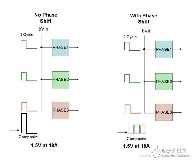
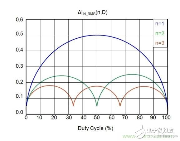
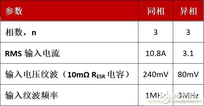
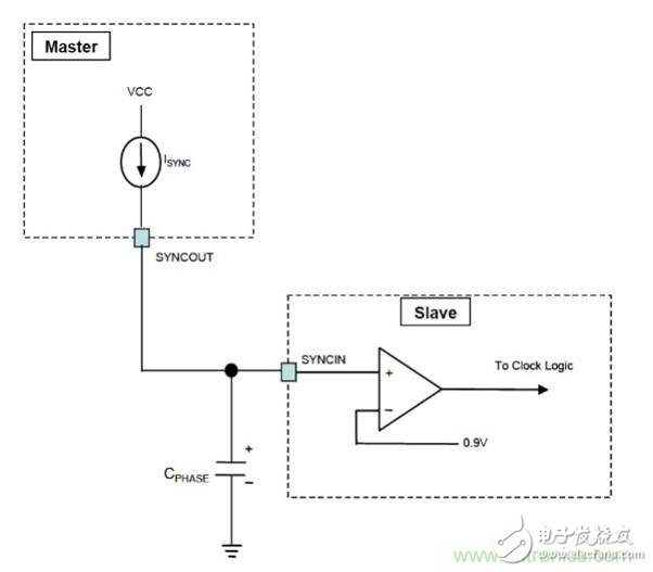
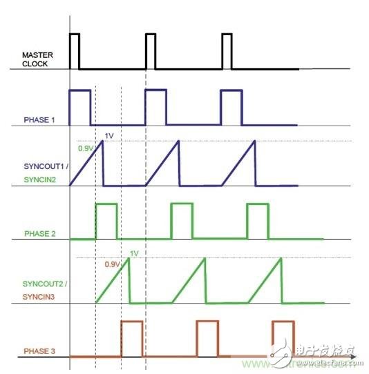
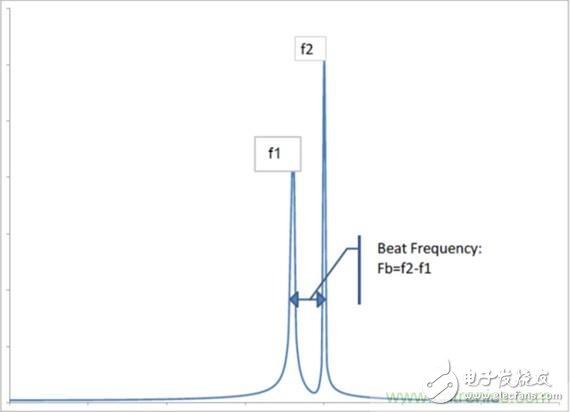
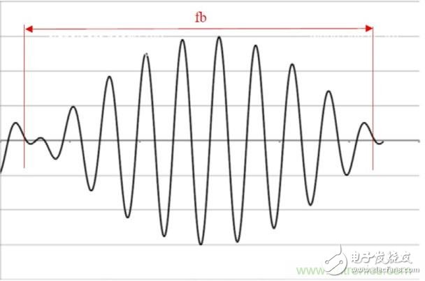
In systems using audio amplifiers, another technical challenge that design engineers must overcome is the "beat frequency", which is the frequency difference between the switching DC/DC converters of the power supply. If the beat frequency is between 100 Hz and 23 kHz, the audio amplifier is likely to detect them and disturb system performance. This article explores how phase shift delay techniques can be used to synchronize multiple DC/DC buck regulators in a master/slave configuration. Phase shifting multiple converters prevents ON time overlap and reduces RMS current, ripple, and input capacitance requirements, which improves system electromagnetic interference and improves power efficiency. This method also eliminates the need for high input filter circuits and solves problems associated with beat frequencies. As shown in Figure 1, converter 1 is a "master" converter that provides the set frequency for the remaining "slave" converters. Figure 1: ISL8018 DC/DC converter application using master/slave configuration. Synchronizing multiple DC/DC converter channels is easier and simpler, but phase shift programming can be a challenge. Figure 2 is a comparison of DC/DC converters in in-phase and out-of-phase configurations. Both designs use a three-phase approach to provide 24A output current. If you want to increase the output current, you can increase the number of phases. In both scenarios, each converter has been optimized for 8A output current. The left side is configured to operate in phase, while the right side is designed to offset each phase by approximately 120°. The three converters on the left have 24A (3&TImes; 8A) peak input ripple or 12A RMS (50% duty cycle). The three out-of-phase working converters on the right have an operating current of 8A or 4.3A RMS (50% duty cycle). Figure 2: Comparison of three-phase DC converters in in-phase and out-of-phase configurations. As mentioned above, the use of phase shifting techniques can significantly reduce input and output capacitance requirements. The RMS input current is specified by Equation 1: Where n is the number of phases, L is the output inductance, Fs is the switching frequency, k(n, D) = floor(n, D), and the return value of the floor function is the largest integer less than or equal to the input value. Figure 3 shows the ΔIIN_RMS(n,D) versus duty cycle. Figure 3: ΔIIN_RMS(n,D) versus duty cycle. Table 1 summarizes the performance comparison of three in-phase working converters and three out-of-phase working converters. Table 1. The out-of-phase scheme has significant advantages over the in-phase design. Synchronous buck regulators (such as the ISL 8018) provide a simple, low-cost way to achieve out-of-phase operation. The SYNCHOUT feature of the main switching regulator provides a current pulse ISYNC at the beginning of each clock cycle. The current source terminates and discharges to 0V after reaching a 1V SYNCHOUT voltage. The detection threshold of the SYNCIN characteristic from the regulator is 0.9V. When each rising edge of SYNCIN reaches 0.9V, its PHASE ON pulse is triggered. Simply add a small, inexpensive capacitor between SYNCIN and GROUND to change the SYNCHOUT current source slew rate. Figure 4 shows a schematic diagram of the master/slave circuit, and Figure 5 shows its logic implementation. The phase shift time (t, in ns) is equal to 2.8·CPHASE (unit pF). Figure 4: Master/slave circuit implementation. Figure 5: Master/slave logic implementation. The implementation of the current source is relatively simple, requiring only 70 square mils of die area. This area can be adjusted to achieve a tolerance of ± 5%. Similarly, the threshold of SYNCIN can be adjusted to ±0.5%. The application capacitance is in the pF range, requiring only a ceramic capacitor with a low-cost NPO or C0G dielectric with a tolerance of ±1%. This phase shift tolerance is approximately 5.12%. As mentioned above, the ISL8018 can be synchronized from the main converter or an external clock. This feature is essential when the operating frequencies of multiple regulators are very close to each other. Figure 6 shows converters 1 and 2 with operating frequencies f1 and f2, respectively. The input shows a "beat" frequency (fb), which is the difference between f1 and f2. If there is no isolation, the fb will appear on GROUND. The output may be as shown in Figure 7, where the envelope is the "beat" frequency. Figure 6: Spectrogram of the input source. Figure 7: Ground ripple voltage noise. Normally the beat frequency is very low, especially when using the same type of converter for multiple power rails. This low level will appear throughout the system. In computing, telecommunications, industrial, or medical device applications that include audio, the system's audio amplifiers are highly likely to receive beat noise. As mentioned above, adding a common mode or differential mode noise filter will increase system design cost. However, the SYNC feature of the ISL8018 DC/DC converter can solve the beat frequency problem by using multiple converters with the same clock frequency. Then fb will be equal to 0 Hz, thereby eliminating the beat frequency in the entire system. Conclusion DC/DC converters such as the ISL8018 can provide a low-cost solution for noise-sensitive applications, especially those that include audio circuits. With phase-shift delay technology, multiple point-of-load (POL) DC/DC converters are used in master/slave configurations to help designers optimize their power supply designs by reducing RMS current, ripple, and input capacitance requirements.
Galvanized monopole tower
1. Based on its shapes, it is generally divided into 5 types: Goblet type, cathead type, cathead type, shaped type and barrel type.
2. Their structural features are: All kinds of towers are of space truss structures; Bard are mainly composed of single equal angle steel or assembling angle steel; Materials are generally Q235(A3F) and Q345(16Mn); Bars are connected by black bolts with shearing force; Entire tower is composed of angle steels, link plates and bolts; A few components like tower base are assemblies of welded steel plates for convenience of hot galvanizing anti-corrosion, transportation and erection.
3. For steel towers that with height below 60m, shackles are mounted on one of main columns for construction people to climb to work. Our Company is a large scale enterprise specializing in manufacturing of 220KV (330KV) electric power steel tower with advanced manufacturing facility and international top-ranking assembly line.
Monopole Tower, Telecommunications Monopole, Steel Monopole Tower, Monopole Transmission Tower,Galvanized Monopole YIXING FUTAO METAL STRUCTURAL UNIT CO.,LTD( YIXING HONGSHENGYUAN ELECTRIC POWER FACILITIES CO.,LTD.) , https://www.chinasteelpole.com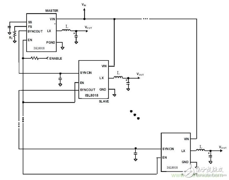
Galvanized monopole Towers are used for a variety of communication applications and are ideal for use when zoning is difficult. Monopoles can also be designed as camouflage poles: pine tree poles, flag poles, palm poles and other stealth towers. Many uses include cellular monopoles, wireless internet monopoles, wifi tower, homeland security monopoles, two-way monopoles, and wind tower monopoles.
Based on application, it can be divided into: Strain tower, straight line tower, angle tower, transposition tower (tower for transposition of wire phase position), terminal tower and crossing tower, etc.
In most step-down power conversion applications where multiple output voltages need to be regulated from a single input source, the switching regulator applies a high input rms when providing point-of-load (POL) power to the FPGA, DSP, and microprocessor. (RMS) current and noise. To solve this problem, design engineers typically use high input filtering (but with additional cost) to mitigate conducted electromagnetic interference (EMI) and/or radiated electromagnetic interference while controlling higher system I2R power losses.