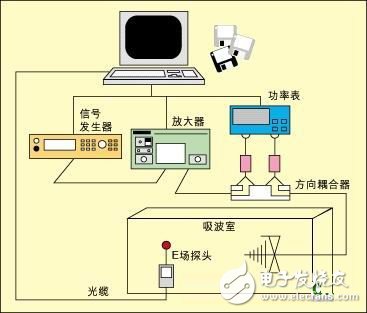
For many years, electromagnetic interference (EMI) effects have been a concern in modern electronic control systems. Especially in today's automotive industry, vehicles use a number of critical and non-critical (CriTIcal and non-criTIcal) in-vehicle electronic modules, such as engine management modules, anti-lock braking systems, and electrical power steering funcTIons. , in-car entertainment system and thermal control module. At the same time, the electromagnetic environment in which the vehicle is located is also more complicated. The electronics on the car must coexist with the RF transmitter. Some of these transmitters are properly installed and set up (for example, in emergency services vehicles), while others are not. (for example, some factory-installed CB transmitters and car mobile phones). In addition, the vehicle may also enter a strong electromagnetic field generated by some external transmitters, the intensity can reach tens or even hundreds of Ford per meter. The automotive industry has been aware of these problems for many years, and all well-known manufacturers have taken certain measures to reduce the impact of electromagnetic interference by establishing test standards and legislative requirements. Therefore, today's vehicles have strong resistance to such interference. However, EMI has a great impact on the performance of on-board modules, so you must continue to be vigilant. Testing of vehicles and their components is a highly specialized field that has always been done by the manufacturers themselves. In some countries, many vehicle manufacturers will jointly fund professional test labs. With the increasing number of sub-components used in vehicles, the trend of outsourcing of components by automakers is becoming more and more obvious. Therefore, EMC testing has gradually become the responsibility of component manufacturers. A number of different test methods and test levels for overlapping frequencies are described in subsections of the International Standard for Immunity Testing of Automotive Components, such as ISO 11452 (International Organization for Standardization) and SAE J1113 (Institute of Automotive Engineers). Vehicle manufacturers can develop their test requirements based on these general standards without any higher legislative requirements. That is, when an automaker wants to develop component-level test requirements for its component suppliers, he can choose the appropriate amount from a list of test methods, test frequency ranges, and test levels to form his own test criteria. Ultimately, a manufacturer that supplies sub-components to multiple automakers may have to test the same components in the same frequency range using different methods depending on different standards. To meet customer testing needs, component manufacturers can use a range of automotive component test systems designed for the RF test specifications included in ISO 11452 and SAE J1113 to help with their work. These test systems are usually self-contained systems that follow the highest level test specifications specified in all standards. With such a system, many of the test instruments used by component manufacturers when testing multiple standards are the same, thus saving a lot of money. Below we will discuss several RF test methods and some of the test parameters specified in the automotive manufacturer's test requirements, and explore how component manufacturers can build the corresponding test system according to the test needs of different customers, to achieve the purpose of testing only the required projects. Several RF test methods To test the RF immunity of an automotive component, RF interference must be applied to it in a manner comparable to how the in-vehicle interference occurs. This introduces the first variable. The car may be exposed to an external field and may carry transmitters and antennas that generate interfering signals, but in any case, the interference field can act directly on where the component is located. For example, when the component is mounted on an open area on or near the dashboard, it creates more interference than when it is installed near the chassis of the vehicle or even in a shielded area inside the engine compartment. many. On the other hand, all electronic modules are connected to the wiring system of the vehicle for the purpose of power supply and signal connection. The wiring device is equivalent to an effective antenna that can be coupled to RF interference, and RF current can be conducted through the connector to the component regardless of where the component is mounted. In view of this, we usually use two test methods: radiation interference test and conducted interference test. Radiation interference test All radiation testing methods do not apply a calibrated RF field to the device under test, so that RF current and voltage can be introduced into the internal structure of the device, and then these RF currents and voltages will appear in the sensitive device. On the node, causing interference in the electronic circuit. Different methods differ in the way they apply RF fields, and each has its own advantages, disadvantages, and limitations. Radiation antenna measurement in microwave darkroom The simplest way to generate an RF field is to inject energy into an antenna and point it to the device under test (EUT). The antenna converts the RF energy into a radiation field and fills it with the test area. Since high-level RF signals need to be generated over a wide spectrum, in order to avoid interference with other legitimate radio users in the vicinity, the test should be performed in a shielded room. But this will introduce reflections from the walls, which will change the field distribution in the room. In order to solve this problem, it is necessary to perform radio wave silencing on the surface of the shielded room to create an "absorber lined chamber" environment, which in turn greatly increases the cost of the test equipment. The antenna used in the test should have a wide frequency response over the measured frequency range. The test frequency in vehicle testing may range from 10 kHz to 18 GHz, so there are many different types of antennas required (see Figure 1). In addition, the field added to the EUT should be as uniform as possible and well controlled. The field at the time of testing may affect the specifications of the darkroom, so the antenna should not be too close to the EUT, and the directivity should not be too strong, otherwise the resulting field will only be concentrated in one area of ​​the EUT. At the same time, the distance between the antenna and the EUT will cause the mutual inductance to increase, which will increase the control difficulty of the signal added on the antenna. The larger the physical size of the object being measured, the more difficult it is to meet this distance requirement. In addition, according to the formula P = (E · r) 2 / 30 watts (when the antenna has unit gain), the farther the antenna is from the EUT, the greater the power required to reach a given field strength. Figure 1 Typical radiation interference test device Note that this formula gives the squared relationship between field strength and distance, that is, when the field strength at a given distance increases from 10 V/m to 20 V/m, the required power is four times the original. Or, when the field strength increases from 10 V/m to 20 V/m, the distance is only a quarter of the original at a given power. The field strength at the EUT position is measured by an isotropic wide-band field sensor. Isotropic is to ensure that the sensor is insensitive to direction, while broadband is to ensure that it can get the correct measurement at different frequencies.
OTG USB Flash Drive is one serial of USB flash drive,which is hot selling right now and widely used on different mobiles,including Iphone and all smart phones which can support OTG function.More and more people choose it since it is quite small and very easy to take with.
There are mainly 4 kinds of OTG USB flash drive as below:
1. 2 IN 1 USB flash drive with micro(or Android)
2. 2 IN 1 USB flash drive with type C.
3.2 IN 1 USB flash drive with lighting for Iphone.
4.3 IN 1 OR 4 IN 1 USB flash drive with lightning/micro/USB C.
Most OTG USB flash drives start with 8GB until 256GB.You may also look for 1TB 2TB OTG USB memory stick but you will find the 1TB 2TB OTG USB flash drive you bought not working soon when you want to save more and more files,or even some files are missing.Why? Because they are not real full capacity!
We only do real full capacity as promised,and no upgrade or fake capacity from us.
otg usb flash drive, otg usb flash drive for apple iphone, best 3 in 1 usb flash drive,best type c usb flash drive,4 in 1 usb memory stick Shenzhen Konchang Electronic Technology Co.,Ltd , https://www.konchang.com