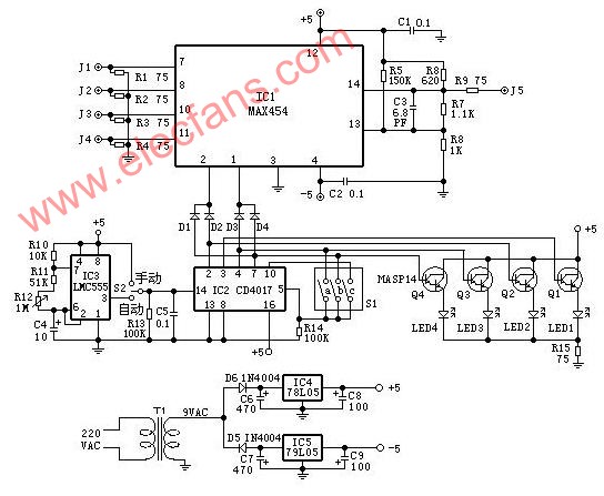
Working principle diagram of self-made video switcher The circuit principle is shown in the figure below. The core of the circuit is a video switching circuit MAX454. It has good quality output image and very low phase distortion. The circuit contains 4 video inputs (IN0 ~ IN3) and a low input impedance line amplifier, driver, two address inputs (A0, A1), a video output and two power terminals. The surveillance lens is connected to the video input of the switch via J1-J4. The 75Ω resistor constitutes the input termination resistance. The gain of the internal amplifier is set by the feedback network connected to pin 13 of IC1. The feedback network consists of R5-R8 and C3. The gain is set to 2 to compensate for the consumption on the terminating resistor R9 (75Ω). Finally, the gain at output J5 is 1. Ningbo Autrends International Trade Co.,Ltd. , https://www.mosvapor.com