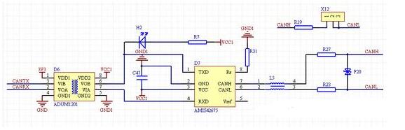
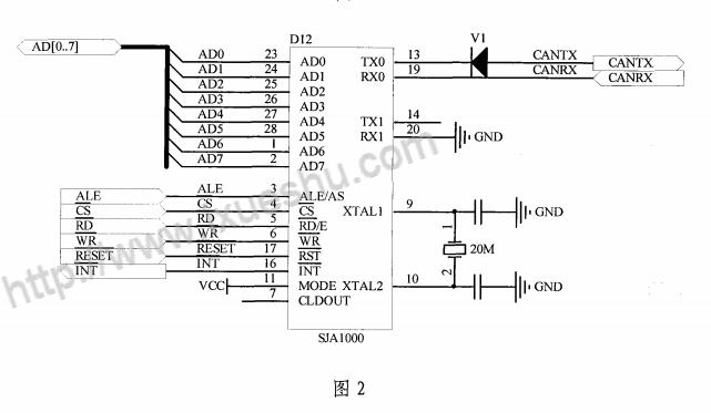
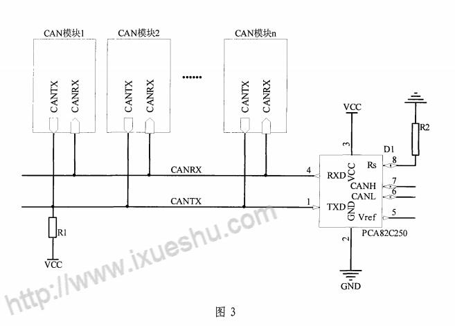
CAN bus communication hardware schematic (using TJA1050T CAN bus driver) F040 built-in CAN bus protocol controller, as long as the external bus driver chip and appropriate anti-jamming circuit can easily establish a CAN bus intelligent monitoring node. This design uses PHILIP's TJA1050T CAN bus driver. CAN bus communication hardware schematic shown in Figure 3. In the figure, the CAN signal receiving pin RX and TX pin of F040 are not directly connected to the RXD and TXD terminals of the TJA1050T, but are connected via the high-speed optocoupler 6N137. The purpose of this is to achieve the electrical performance of the CAN bus nodes. isolation. In order to achieve full electrical isolation in the true sense, the VA and VB of the optocoupler must be isolated by a DC-DC module or a switching power supply module with multiple isolated outputs. To prevent overcurrent surges, the TJA1050T's CANH and CANL pins are each connected to the bus by a 5Ω resistor. Two 30P capacitors are connected in parallel between CANH and CANL feet and ground to filter out high-frequency interference on the bus. The lightning protection tubes D1 and D2 can provide protection against transient interference. The 8 pins of the TJA1050T are connected to one port of the F040 for mode selection. The TJA1050T has two operating modes for selection, high speed mode and silent mode. The TJA1050T operates normally in high-speed mode, while in the silent mode, the TJA1050T transmitter is disabled and performs the listen-only function, which can be used to prevent network congestion caused by the CAN controller losing control. CAN bus communication typical circuit (with isolation) CAN is an abbreviation of Controller Area Network (CAN). It was developed by German company BOSCH and eventually became an international standard (ISO 11898). It is one of the most widely used field buses in the world. Its typical application is in the automotive field. Below we share a typical CAN bus circuit. The ADUM1201 achieves the isolation effect in the figure. The CAN level conversion chip is implemented by AMIS42675. Figure 2 is a schematic diagram of a controller portion of the invention Figure 3 is a schematic diagram of the bus portion of the present invention detailed description The following describes the present invention in detail with reference to the above figure: The communication circuit of the CAN bus of the present invention includes two parts of the circuit, the first part is the line and circuit of the CANTX signal output by the CAN controller; the second part is the CAN transceiver circuit. 1) The schematic diagram of the line and circuit of the CANTX signal output by the CAN controller is shown in Fig. 1 (taking SJA1000 as an example). First, assume that there is only one CAN controller on the bus. If the controller's TXO pin is high, a pull-up resistor is included on the CANTX bus (see Figure 2 for R1). So at this time, the CANTX bus will also be high; if the TXO pin is low, the diode is turned on after R1 current limiting, and the CANTX bus will also be pulled down to the turn-on voltage of the diode (usually 0.7V) ), the bus will be low. Therefore, after the diode has passed, the state on the CANTX is the same as that of the TXO pin of the CAN controller. Second, if there are multiple CAN controllers on the CANTX bus, if the TXOs of the two controllers output high level and low level respectively, then the TXO of the high level controller outputs a diode in series due to the reverse direction. Therefore, it does not form a loop with the TXO that outputs a low-level controller, thereby avoiding a short circuit on the bus. Solved the problem of CAN controllers not directly interconnecting with CAN transceivers. In addition, the transmit pins of some CAN controllers can be directly configured to open-drain states. In this case, the diode V1 connected in series in the circuit can be omitted. 2) The schematic diagram of the bus part of the circuit is shown in Figure 2 (taking the PCA82C250 as an example). A pull-up resistor is required on the CANTX bus to pull the bus up to a certain high level. Since the CAN bus adopts a transmission monitoring mode, a CAN transceiver needs to be added at the end of the bus so that the CAN controller can monitor the data on the bus, which satisfies the conditions for normal transmission and reception of the CAN controller. Although the present invention has been disclosed in the above preferred embodiments, it is not intended to limit the present invention. Any technical solution obtained by adopting equivalent substitutions or equivalent transformations falls within the protection scope of the present invention. About 51 single-chip CAN bus communication circuit diagram Incremental Encoder is commonly used, and Absolute Encoder is used if there are strict requirements on position and zero position. Servo system should be analyzed in detail, depending on the application situation. Commonly used incremental encoder for speed measurement, which can be used for infinite accumulation measurement; Absolute encoder is used for position measurement, and the position is unique (single or multiple turns). Finally, it depends on the application situation and the purpose and requirements to be realized. Incremental Linear Encoders,Linear Optical Encoder,Linear Position Encoder,Encoder Bearing Tester Yuheng Optics Co., Ltd.(Changchun) , https://www.yhenoptics.com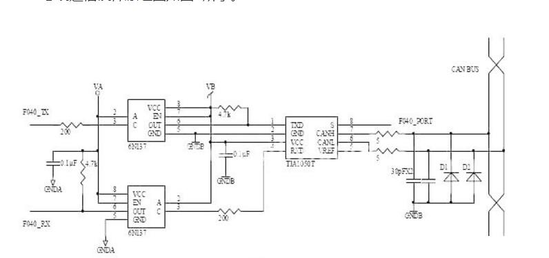
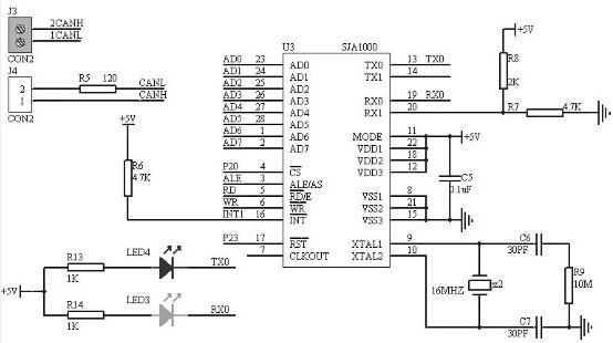
CAN bus communication typical circuit diagram (1)