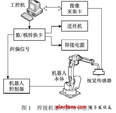
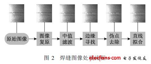
Ninety percent of the welding robots currently in service work in the “teaching reproduction†mode, and a few work in trajectory planning. During the welding process, there is a certain error between the welding torch and the center of the weld, and the welding process is a complex, non-linear, and interfering process. The hot deformation, undercut, misalignment, and weld gap change of the welded workpiece. It is unpredictable, and these factors will directly affect the quality of welding. On the basis of "teaching reproduction" or trajectory planning application, real-time weld rectification can further improve the welding precision, especially suitable for the workpiece production which is difficult to control by automatic welding such as welding deformation and assembly complexity in auxiliary engineering. In this paper, based on the butt welding of the new spacecraft fuel tank LF6 aluminum alloy 2 mm thin plate, for the pulse tungsten inert gas shielded welding (GT AW) welding method, the seam tracking test is carried out on the flat straight and flat flanges. The traditional "teaching reproduction" type robot was developed into an arc welding robot system with real-time weld tracking. 1 test part 1. 1 test system composition In this experiment, the actuators include HP6 welding robot from Japan Yaskawa Electric Corporation, two-axis flip positioner, single-axis head-to-tail positioner, and IN VERTERELESON 500P AC/DC dual-purpose GT AW produced by Japan OT C. Welding Power Supply, CM-271 wire feeder and HC-71 wire feeder control box. The control system is the industrial computer of Advantech Co., Ltd. The sensing system is a self-developed CCD passive optical vision system and an image acquisition card. The entire system is shown in Figure 1. 毫米. The welding speed is 2. 6 mm / s. The welding frequency is 2 Hz, the pulse current is 2 Hz, the base current is 50 A, the peak current is 125 A, and the welding speed is 2. 6 mm / s. 1. 2 image acquisition and processing 1. 2. 1 open small window analysis The "small window" is used to obtain the weld feature information, and a small window of 100 frames x 120 frames is opened in the weld area, and only the image in this window is processed. This window contains the feature information needed to perform weld tracking and reduces a large amount of unnecessary image information. The CCD camera and the wire feeder are fixed on the welding gun, that is, the relative positions of the welding gun, the tungsten electrode and the wire feeder on the image plane are unchanged, and the axis of the CCD camera, the axis of the welding torch, and the The weld is adjusted to the same plane, so that the projection of the axis of the torch on the image plane is a horizontal line, which provides a convenient condition for subsequent tracking. 1. 2. 2 image processing algorithm In the test, the upper and lower edges of the weld are first extracted, and after the pseudo-point is removed, the least squares fitting is performed to obtain the weld center line. The image processing algorithm flow mainly includes image restoration, median filtering, edge finding, pseudo-point removal and least squares fitting, as shown in Figure 2. The inverse filter method is used for image restoration, and 3x3 template median filtering is used. The gray value of the current pixel is obtained by the intermediate value of the gray value of its 8 neighborhood pixels. After observing and analyzing the image, it was found that the edge of the weld was greatly changed in gray scale compared with other areas. Therefore, the weld edge points are determined according to the rate at which the gradation value changes, that is, the two points at which the rate change is the largest in each column as the upper and lower edge points of the weld. This edge detection algorithm is based on the characteristics of a 2 mm thin plate. Without the bevel, large gray scale changes at the weld are easily captured in the entire image, and the smaller calculation amount of such an algorithm does not affect the calculation. Real-time image processing. After the above image processing, the weld edge is not accurately obtained, and there are still false edges. How to remove the false edge points and identify the true weld edge is the most difficult and most critical technology in image processing. The pseudo edge points are removed by scanning the 24 neighborhoods from the upper and lower directions to the middle by progressive scanning. Since the edge of the weld is continuously changed, it is assumed that the image processing error is within 2 pixels. If there is no adjacent feature point in the neighborhood of a certain feature point 24, the point is considered to be a false edge point or an isolated point. Featuring Level VI energy efficiency and meet IEC/EN/UL 62368-1 safety standards, the external AC to DC power adapters are available in variety of international different AC input blade versions for United States, Europe, Korea, U.K. and Australia, and provides 8 safety protections. The 13 to 24 wattage series wall mount power adapters follows the PC flame retardant plastic case and 3 years warranty. 13 ~ 24 Watt Wall Plug Adapters Plug Adapter,12V Ac Adapter,Universal Wall Adapter,Wall Switching Adapter,Power Plug Adapters,100V-240V Plug Adapter Shenzhenshi Zhenhuan Electronic Co Ltd , https://www.szzhpower.com