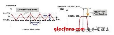
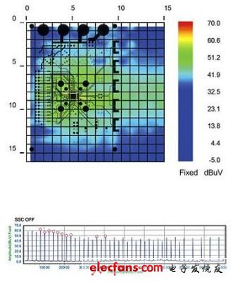
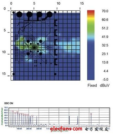
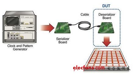
Industry-leading TEMPO evaluation service High segmentation capability, high-performance chip fuses Designed for OEM designers and engineers. Samtec connector complete signal source every day new product moments new experience complete 15A switch mode power supply global certification Performance chip fuse FRAM iron-iron non-volatile random access memory Automakers often use the latest consumer electronics systems to differentiate themselves from other manufacturers' cars, which must work in all the harsh conditions. Power systems, safety systems, and other automotive control systems all have the same requirements, and in the event of a failure, these systems can have even more serious consequences. Automotive electronics systems are particularly sensitive to the electromagnetic radiation of chips and printed circuit boards supplied by suppliers. Therefore, SAE (formerly the Society of Automotive Engineers) has defined test specifications and established requirements for electromagnetic compatibility (EMC) and electromagnetic interference (EMI), and has continuously improved it. Using very near-field EM scanning technology, the supplier's design team can measure and immediately display the spatial and spectral characteristics of the radiation through a desktop system, avoiding problems later in higher-cost module, system or vehicle-level testing. This article discusses several examples that demonstrate the value of this test. The first example is about the radiation characteristics of the Spread Spectrum Clock Generator (SSCG), which are scanned under "off" and "on" conditions, respectively. In the second example, the design team compared the second-generation half-duplex serial deserializer (serializer/deserializer) system with the third-generation full-duplex system. The results validate the next generation of features and their benefits, not only helping customers reduce time to market, but also have a positive impact on customers. Very near field EMI scanning technology The fast magnetic near-field measuring instrument captures and displays visible images of the spectrum and real-time spatial scan results. Chip manufacturers and PCB design engineers can scan any board and identify constant or time-base sources in the 50kHz to 4GHz frequency range. This scanning technology helps to quickly solve a wide range of electromagnetic design problems, including filtering, shielding, common mode, current distribution, immunity to interference, and broadband noise. During the development of any new PCB, the design engineer must identify the radiator or RF leakage outside of the design and describe and process it to pass the conformance test. Possible radiators include high speed, high power devices and devices with high density or high complexity. The scanning system displays spatial radiation characteristics in a superimposed manner on Gerber files, so testers can pinpoint the source of all radiation problems. After the design engineer has taken the appropriate action, the design engineer can re-test the device and immediately quantify the effect of the calibration design. The scanning system consists of a scanner, a small adapter, a customer-provided spectrum analyzer, and a PC running the scanning system software. The benchtop scanner includes 2,436 loops that produce 1,218 magnetic field probes spaced 7.5 mm apart to form an electronic switch array and provide resolutions up to 3.75 mm. The system operates from 50kHz to 4GHz and is enabled with an optional software key. This allows users to test the design themselves without having to rely on another department, test engineer, or time-consuming off-site testing. Engineers can even make changes to the design after diagnosing an intermittent failure and test it again soon. The results of the test can be accurately verified for the impact of design changes. With the scanning system, board designers can pre-test and resolve EMC issues to avoid unanticipated compliance results. The scanner's diagnostic capabilities help the design team reduce radiation test time by more than two orders of magnitude. EMI near-field radiation characteristics: SSCG example A large semiconductor manufacturer implemented the SSCG function on the parallel bus of the deserializer. The SSCG function can reduce radiation by extending the peak energy of the radiation over a wider frequency band. As shown in Figure 1 below, the frequency change occurs near the nominal clock center frequency (central spread spectrum modulation) and the spread spectrum is positive or negative 1.0% (fdev). At the receiver parallel bus, the output modulates the clock frequency and data spectrum over time at a modulation rate of kilohertz (fmod). The target customers of the customized serial deserializer chipset are automotive manufacturers that require low EMI radiation characteristics for the installed electronics. Figure 1: Spread spectrum clock function. The company expects to demonstrate convincing quantitative evidence to automakers that SSCG functionality can effectively reduce EMI emissions. To achieve this goal, the design team first placed the device under test (DUT) on its internal scanner with the SSCG function "off", powered it up, and then captured the radiation characteristics in the PC. For effective comparison, the same device under test is scanned with the SSCG function turned on. The very near-field scanning system displays and generates the following radiation characteristics after spatial and spectral scanning. It should be noted that the scan results are superimposed on the Gerber design file, so that the analysis of the results can immediately determine the specific radiator in the device under test. Figure 2 shows the radiation characteristics of the device under test when the SSCG function is "off". Figure 2: EMI radiation characteristics measured when the SSCG function is "off". Figure 3 shows the spatial and spectral (amplitude and frequency) characteristics of the device under test when the SSCG function is "on". By comparison, it can be found that the radiation has been significantly reduced. Figure 3: EMI radiation characteristics when the SSCG function is "on". After comparing the test results, the design team found that the electromagnetic radiation was significantly reduced due to the use of the SSCG function. The biggest challenge for automotive electronics engineers is to reduce EMI emissions. Every time the customer support team showed these results to automaker customers, they generally showed great interest. Any EMI reduction feature (SSCG functionality in this case) can reduce time to market, reduce shielding and cost. EMI near-field radiation characteristics: a new generation serial deserializer example This is the second example of a semiconductor supplier that has developed a second-generation chipset solution for point-to-point transmission via a serial deserializer. In the third generation chipset, the design team adopted a different technology and upgraded the transmission capacity. They embed the bidirectional control channels together in a high-speed serial link for bidirectional transmission (full duplex). To quantify the radiation characteristics of the half-duplex deserializer and the new generation full-duplex design, the design team used the internal EMI very near-field scanner again. They placed the original half-duplex plate on the scanner for baseline measurements. After powering up the devices under test, they activated the scanner on the PC. (See Figure 4) Figure 4: Test environment for EMI scanning of half-duplex and full-duplex serial deserializer devices. Using the same test setup, the design team replaced the baseline board with a new generation of full-duplex chipset boards, while maintaining the same specifications for each feature. As noted above, it is important to note that spatial scans are superimposed on each generated Gerber design file to help engineers determine any sources of radiation present. Lithium Battery Charger can charge 3.7V LiPo battery at a rate of 500mA,1000mA, 1500mA or 2000mA per hour. It is designed to charge single-cell Li-Ion battery or battery packs Li-Polymer batteries. The charger board incorporates a charging circuit, status LED with changetable color to let you know when battery is full. Please double check the data sheet when you need to buy a battery charger . Lithium Battery Charger Lithium Battery Charger,18650 Battery Charger,Lithium Car Battery Charger,Portable Lithium Battery Charger Meile Group Limited , https://www.hkmeile.com