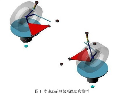
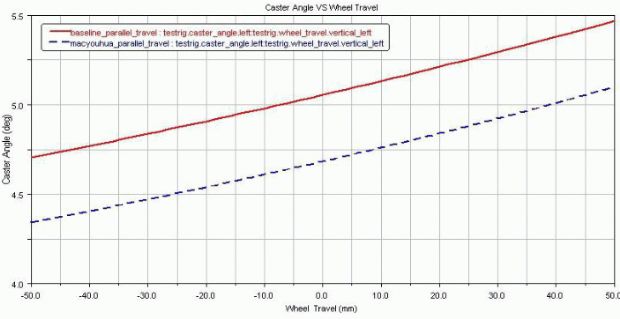
Abstract: In order to deeply study the dynamic performance of the MacPherson suspension system, based on multi-body system dynamics theory, the multi-body dynamics software ADAMS/CAR is used to construct the MacPherson suspension model. This paper uses the Insight module to do hard point parameters. Optimization, parallel wheel jump simulation analysis before and after optimization, comparing the characteristic parameters affecting vehicle stability before and after optimization. The results show that in ADAMS/CAR, the overall performance of the suspension is greatly improved by the optimization of the suspension hard point coordinate parameters, which provides an improved theoretical basis for the design and manufacture of the MacPherson suspension. This article refers to the address: http:// I. Introduction In the automotive industry, traditional designs generally use empirical design, mathematical derivation, and geometric mapping. Although the design requirements are met, accuracy and efficiency are not high. With the fierce competition of modern competition, people gradually realize that the most effective way to improve product quality, shorten product development cycle and reduce product development cost is to apply simulation tools for system level design. With the widespread use of tools such as computers, virtual prototyping technology has been greatly promoted. The ADAMS/CAR multi-body system dynamics analysis software is a complete vehicle design package developed by MDI and Audi, BMW, Volvo and other companies. It integrates their expertise in automotive design and development to help engineers quickly build high precision. The whole vehicle virtual prototype. It has rich modeling functions and powerful kinematics and dynamics solving ability. It can build a large-scale, complex system-level simulation model, which can simulate and analyze the performance of suspension and vehicle performance. The most widely used is the MacPherson suspension. Compared to other independent suspensions, the MacPherson suspension simplifies the structure, reduces the mass, saves space, reduces manufacturing costs, and takes up almost no lateral space. Conducive to the construction of the front floor of the car and the engine layout, it has an unparalleled advantage in the front suspension of the compact car. In addition, the number of hinge points of the MacPherson suspension is small; there is a large distance between the upper and lower hinge points, and the distance between the lower hinge point and the wheel ground point is small, which is advantageous for reducing the force at the hinge point; The spring travel is large. When the wheel jumps, the track, the toe angle and the camber angle of the wheel do not change much, which reduces the wear of the tire. These characteristics make the vehicle have good driving stability. The McPherson suspension simulation model was built by ADAMS/CAR. The key hard point parameters affecting the suspension performance were optimized by ADAMS/Insight. The suspensions before and after optimization were simulated and analyzed. The lead deviation before and after optimization was compared. Suspension performance parameters such as toe angle, wheel camber angle. The research results show that the optimized suspension handling performance has been greatly improved. Second, the simulation model is established Before establishing the MacPherson suspension model, a reasonable mathematical model must be simplified for the suspension system: the entire McPherson suspension is simulated as a multi-rigid system, and the inertial forces of the rigid bodies of the system in all directions are zero; The restraint of the force of some hinges in some directions is relatively small, the influence on the dynamics of the vehicle is negligible, and it is assumed to be zero; the damper is simplified to linear spring and damping, and the friction in each pair is neglected. Excluded; the focus of this paper is on suspension, and the tire is simplified to a rigid body. When establishing the multi-body simulation model, the coordinate origin of the MacPherson suspension virtual prototype is the midpoint of the line connecting the center points of the grounding marks on both sides of the wheel. Taking the ground as the XY plane, the symmetry plane of the center of the car is the XZ plane. The front wheel center line is connected, the planes of the vertical XY and XZ planes are the YZ plane, and the vertical direction is the Z-axis forward direction, and the right side of the vehicle body is the Y-axis plane. In the positive direction, the opposite direction of the car's heading direction is the X-axis forward direction. The hard point is the key geometric positioning point at the joint between the parts. The hard point is determined by giving the geometric position of the joint between the parts in the subsystem coordinate system. The spatial position coordinates and correlation coefficients of the critical hard points of the model are the key to establishing the kinematics model. The coordinates of the hard points can be obtained from the assembly drawings provided by the manufacturer. Calculate or measure the mass of the integrated part, the position of the centroid, and the moment of inertia around the three coordinate axes of the centroid coordinate system. Fill these kinetic parameters into the corresponding inputs. Create a geometric model based on the hard point, define the motion relationship between the parts, determine the constraint type to connect the parts to form a template, then generate the template, and then assemble the test bench with the test bench to complete the suspension test system model. The virtual prototype simulation model of the MacPherson suspension in Adams/Car is shown in Figure 1. Third, system dynamics simulation analysis After assembling the suspension model and the test bench, the McPherson suspension was tested in the same direction parallel wheel runout. The up and down jump distance of the suspension is set to 100mm, and the variation of the main performance parameters during the suspension jump is calculated by the left and right wheels synchronously jumping up and down. Since the main performance parameters of the left and right wheels have the same trend during the beating process, only the left wheel is selected as the research object. During the movement of the whole vehicle, due to the certain unevenness of the road surface, the relative position between the tire and the vehicle body will change at this time, which will also cause relative changes in the wheel positioning parameters, if the wheel positioning parameters change too much. In this case, it will aggravate the wear of the tires and steering parts and reduce the handling stability and other related performance of the vehicle. Therefore, the amount of change in the parameters associated with the wheel alignment parameters of the suspension system cannot be too large. The optimization of the suspension utilizes ADAMS/Insight to optimize the analysis of some key hard points of the suspension. Since the parameters of the suspension system and the wheel positioning parameters cannot be changed too much, the optimization of the hard point parameters can only be carried out in a small range. After several iterations of the iteration, the optimization parameters are obtained. The model is corrected with the optimized hard point coordinates, and the parallel wheel jump simulation is performed again. 2, 3, 4, 5, and 6 are graphs of wheel camber angle, kingpin caster angle, kingpin camber angle, kingpin offset, and front wheel toe angle before and after optimization, respectively. In Figures 2 to 6, the red curve is derived from the unoptimized McPherson suspension simulation test, and the blue is obtained from the McPherson suspension simulation test after optimizing the hard point coordinates. The results of the comparative study show that the optimized performance parameters are much better than those before optimization. (1) camber angle Figure 2 Comparison of wheel camber angle before and after optimization (red is not optimized, after blue optimization) In order to prevent the over-steering or over-steering trend of the wheel, it is generally desirable that the wheel will jump from -2 to 0.5 in the range of ±50 mm from the full-load position. It can be seen from Fig. 2 that the unoptimized McPherson suspension wheel camber angle ranges from -0.75 to 1.25, which fails to meet the design standard in steering stability, and the optimized McPherson suspension wheel camber angle variation range From 0 to 0.47, the variation is greatly reduced, and the maximum value is also reduced, so that the parameters meet the design requirements, and the tendency of insufficient steering or excessive steering is reduced, and the driving stability of the vehicle is enhanced. (2) caster angle (caster angle) When the caster angle is positive, it has the effect of suppressing the nodding moment when braking, ensuring that the wheel has a proper returning moment, and the wheel is reset to improve the stability of the straight running of the whole vehicle. The caster rear inclination angle does not change greatly during the up and down movement of the wheel, so as to avoid the phenomenon that the returning moment is too large or too small when the load changes, and the steering stability is deteriorated. However, if it is too large, the counter-torque of the wheel support will be too large, resulting in wheel wobble or steering wheel force change. Generally, the caster angle is required to be between 4° and 6°. The curve shown in Figure 3 shows that the unoptimized suspension caster caster angle is between 4.7 and 5.4, and the optimized between 4.2 and 5.2, although both meet the design requirements, but the optimized caster caster angle The smaller value is beneficial to suppress the braking nodding and improve the straight running stability of the suspension system. Figure 3 Comparison of the caster angles before and after optimization (red is not optimized, after blue optimization) (3) kingpin inclination angle The kingpin internal tilt angle can make the car steering automatic return and the steering operation light. When the wheel jumps, the kingpin internal inclination angle changes greatly, which will make the steering heavy and accelerate the tire wear. In actual design, the approximate range is 7 to 13, and it is desirable to take a smaller value. Therefore, the design requires that the caster angle of the kingpin should not be too large. It can be seen from Fig. 4 that the optimized caster angle of the MacPherson suspension is the same as the caster angle of the kingpin, although the change trend does not change much, but the amplitude decreases. The steering ability of the car is improved, the steering operation is lighter, and the wear of the tire is reduced. Figure 4 Comparison of the caster angles of the kingpin before and after optimization (red is not optimized, after blue optimization) (4) The main pin offset (scrub radius) When the car is turning, the steering wheel rotates around the kingpin, and the resistance torque of the ground to the steering is proportional to the magnitude of the kingpin offset. The smaller the kingpin offset is, the smaller the steering torque is. Therefore, the design requirements generally require the kingpin offset. Smaller to reduce steering effort and ground impact on the steering system. The kingpin offset is closely related to the kingpin tilt angle. Different kingpin offsets can be obtained by adjusting the caster pitch angle. It can be seen from Fig. 5 that the deviation of the kingpin before optimization is between 13 and 23.5. However, after optimization, the deviation of the kingpin is between 2.9 and 19, and the amplitude is greatly reduced. The suspension performance and the stability of the vehicle are improved. There has been a significant improvement. Figure 5 Comparison of the main pin offset before and after optimization (red is not optimized, after blue optimization) (5) Front wheel toe angle (toeangle) The role of the toe angle of the wheel is mainly to reduce the adverse consequences caused by the front wheel camber and the longitudinal obstruction force causing the front end of the front wheel to roll outward. For the front wheel of the car, the toe angle value of the beating on the wheel is mostly designed to change around zero. The design value is taken near zero to control the toe change caused by the unevenness of the road surface during straight running, ensuring good straight running stability. In addition, the change of the weak negative toe is to make the vehicle obtain weak understeer characteristics. When the wheel is running, the change of the toe is too large, which will affect the straight running stability of the vehicle, and increase the rolling resistance between the ground and the tire. Therefore, the design principle of the toe angle is when the wheel jumps. The smaller the amount, the better. As shown in Fig. 6, the variation amplitude of the MacPherson suspension is greatly reduced, the linear stability is enhanced, and the suspension performance and vehicle handling stability are improved. From the comparison of the above five parameters, it can be seen that the optimized MacPherson suspension has significant improvements in various parameters, and the overall system performance and vehicle handling stability have to be improved a lot. The design and manufacture of the MacPherson suspension provides an improved theoretical basis for guiding the actual suspension design process. However, due to the limitation of the body arrangement, the optimization of the hard point coordinate value can only be limited to a certain small range, and the obtained optimal value is also a relative value, not an absolute optimal value. Figure 6 Comparison of front toe toe angles before and after optimization (red is not optimized, after blue optimization) Fourth, the conclusion Based on the multi-system dynamics software ADAMS/CAR, based on the multi-system dynamics theory, the McPherson suspension model is constructed in ADAMS/CAR, and the dynamic parameters of the characteristic parameters affecting the vehicle's handling stability are analyzed and the hard point parameters are analyzed. Optimized, the coordinate optimal value of the key hard point can be obtained through optimization. The results show that in the ADAMS/CAR, the stability of the suspension can be improved by the optimization of the coordinates of the hard point coordinates of the suspension, which provides an improved theoretical basis for the design and manufacture of the MacPherson suspension, and the actual suspension design. The process has a guiding role.
Flex-Rigid PCB, it's the PCB that part of it is rigid and part of it is flex. It combine flex PCB and rigid PCB in a same PCB together and we call it flex-rigid PCB or rigid-flex PCB. Normally, the rigid PCB area is for soldering electronic components and the flex PCB area would be taken as cables to connect rigid PCB areas together, this could make the rigid-flex PCB perfectly suit for a wide range of applications.
PCB = printed circuit board and PCBA = printed circuit board assembly. For PCB, it means the copper circuits be printed on a board, and so the main composition of PCB are copper and board.
The copper is the circuits material and the circuits designed by the PCB designers. Depends on the current in the circuits, the PCB copper thickness could be done with 0.5oz-10oz. But the PCB designers need be noted that the copper track width/space need be enlarged with the thickness. For example, the minimum copper track width/space could be 3mil/3mil with 0.5oz, but would be 4mil/4mil with 1oz.
The PCB board could be rigid PCB, could be flex PCB and also could be flex-rigid PCB. And the materials could be FR4, PI, Aluminum, Copper-based, Rogers, Teflon, etc. They have different applications. For example, FR4 PCB is the most commonly used for rigid PCB and almost good for all electronics products; PI is the most commonly used for flex PCB; Aluminum and copper-based have good thermal diffusivity and always used for LED PCB ; Rogers PCB and Teflon PCB are always used for High Frequency PCB, etc.
We are the one-stop shop for all kinds of PCB manufacture service from PCB Prototype to big volume, which could save our customers a lot of time and money.
PCB Manufacture Capabilities
Features
Capabilities
Layers
1-36 layers
Material
FR-4, Aluminum, Copper, Polyimide, high frequency (Rogers, PTEE, PI), etc.
PCB Type
FR-4 Standard PCB , Aluminum PCB , Copper-based PCB, HDI PCB , Rigid-Flex PCB, Flex PCB, Thick Copper PCB and Rogers PCB, etc.
Board Thickness
0.1mm-6.0mm
Copper Thickness
1/2oz-6oz(18um-210um)
Biggest Board size
600mm*1200mm
Min Tracing/Spacing
0.075mm/0.075mm (3mil/3mil)
Min drilling Hole diameter
0.15mm(6mil), 0.1mm(4mil)-laser drill
Solder Mask
Green, Black, White, Red, Yellow, Blue and Purple, etc.
Silkscreen color
White, Blue, Black, Red, Yellow
Surface finish
HASL Lead free, Immersion Gold (ENIG), Immersion Tin, Immersion Silver, OSP, Carbon oil, etc.
Special Techniques
Impedance Control, Gold Fingers, Blind/Buried vias, Peelable solder mask, Half holes, Via-in-Pad and Countersink hole, etc.
PCB Products Show
PCB Factory Show
Flex-Rigid PCB Flex-Rigid PCB,Multilayer Rigid-Flex PCB,Rigid Flex PCB,Rigid Flex PCB Board ZhongFeng Electronic Technology Co., Limited , https://www.dopcba.com