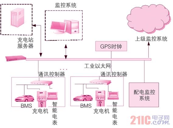
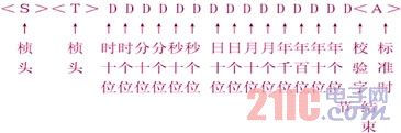
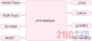
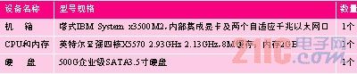
1 Introduction This article refers to the address: http:// Due to the renewability and cleanliness of fuel, electric vehicles have gradually become the target of the country's vigorous development in the new energy automobile industry, and the electric vehicle charging station is the infrastructure that must be built after the large-scale industrialization of electric vehicles. In the construction of charging stations, the realization of its efficient, safe and intelligent management has become the mainstream. As the core of the charging station automation system, the charging station monitoring system is an important topic and hotspot of the current electric vehicle charging station construction industry research. This paper first introduces the structural design of the charging station monitoring system based on the dedicated parking lot, designs the functions realized by the monitoring system according to the national standard, and finally introduces the realization of the charging station monitoring system based on mcgs technology. 2 Charging station monitoring system structure design Referring to the guidance of the State Grid Corporation's electric vehicle charging facilities, the typical design of electric vehicle charging facilities, the technical realization route and development trend of the power monitoring system, the charging station monitoring system is designed by combining c/s and b/s. 1 is shown. Figure 1 Structure diagram of the charging station monitoring system The entire monitoring system uses industrial Ethernet connection. The charger, bms (battery management system) and smart meter are converted by the communication controller to the Ethernet and communicate with the host computer. The power distribution monitoring system is also controlled by Ethernet and monitoring. System communication, these parts adopt c/s structure; the superior monitoring system communicates with the local monitoring system through Ethernet, this part adopts b/s structure; the server is responsible for storing various data information in the charging station, and the GPS clock provides local clock calibration function. The monitoring system enables access to various types of chargers via Industrial Ethernet and monitors the charger and battery management system. In addition, the local monitoring system can communicate with multiple superior monitoring systems via Ethernet to achieve hierarchical and remote monitoring. This structure makes the system more scalable and can meet the requirements of continuous expansion of charging facilities. 3 monitoring system function design The core function of the charging station monitoring system is the charging monitoring function, which monitors the various working states of the charger and the rechargeable battery. In addition, some auxiliary functions are included to enhance system robustness and intelligent management. 3.1 Data Acquisition Function The system collects the working state of the charger (charging mode), temperature, voltage (output voltage, DC bus voltage), current (output current, DC bus current), power and fault signal (input voltage overvoltage, input voltage undervoltage, input current) Overcurrent, output voltage overvoltage, output current overcurrent, module temperature too high, input phase loss, communication interruption, fan failure, etc.); collection of battery pack temperature, soc, terminal voltage, terminal current, battery connection status and battery failure Signal (including single battery operating parameters, such as normal working voltage, temperature, capacity, energy, battery voltage upper limit, lower limit alarm limit, temperature alarm upper limit, maximum charging current and current alarm upper limit, voltage difference maximum alarm upper limit, charging times, Battery Health Index); collects the switching status, protection signal, voltage and current, active power, reactive power and power factor of the charging station's power distribution system. 3.2 Control adjustment function The monitoring system can issue control commands to the charger, start and stop the remote control charger, check the time, emergency stop, remotely set the charging parameters, and control the switching of the circuit breaker and switch of the power distribution system. 3.3 Data processing and storage functions The monitoring system classifies and stores according to the nature and importance of the data in the charging station. When the amount of data is large, real-time transmission of important information can be guaranteed according to a predetermined strategy; real-time data such as telemetry, remote signaling, alarm events, etc. of the charger and the battery pack are provided. Centralized storage and query function of historical data; in addition, the system has operation record, system fault record, charging operation parameter abnormal record and battery group parameter abnormal record function. 4 charging station monitoring system implementation 4.1 gps clock system The system uses the k806-d satellite synchronous clock of Shanghai Ruicheng Co., Ltd. In addition to the universal serial port, the clock also provides two-way network timing signals. The system has strong self-maintaining capability (better than 0.6us/min) and supports many Operating systems and network devices such as routers, switches, and intelligent controllers based on the NTP protocol support power interruption, gps out-of-step dry contact signal alarms, stable operation, and easy operation. In the charging station monitoring system, the time format used by the gps clock timing is shown in Figure 2. Figure 2 time format of gps clock timing 4.2 Communication Controller The charger uses the CAN bus to transmit data. It does not provide conversion between the CAN bus signal and the Ethernet signal. The upper monitoring computer uses Industrial Ethernet communication, so the communication controller is used between the monitoring computer and the charger to be monitored. To complete this conversion. The controller mainly includes hardware platform design and software system design. 4.2.1 Hardware Design The hardware platform is based on Atmel's at91rm9200 chip. This industrial-grade chip embedded network controller includes Ethernet mac control, so only one external 10/100m physical layer chip dm9161e can provide an Ethernet access channel. The bus interface is composed of the can controller chip mcp2515 and the high-speed can bus transceiver tja1050 [1]. The mcp2515 and at91rm9200 are connected via the standard serial peripheral interface spi (at91rm9200 embedded). It supports the canv2.0b specification, which can send and receive standard and extended information frames, as well as receive filtering and information management. The function. The tja1050 is a high-speed CAN bus transceiver that is compatible with the mcp2515. It is responsible for the receive and transmit level transitions between the node and the bus. In addition, in order to enable the hardware platform to provide an efficient software operating environment, the system also designed a storage circuit (16mb nor flash, mainly used to store the system bootloader bootloader, kernel, file system; 64mb nand flash for storing data; 32mb sdram, Provide kernel and application runtime space, reset circuit, jtag debug interface and rs485 extended serial port. The system structure is shown in Figure 3. Figure 3 Communication controller hardware block diagram 4.2.2 Software Design The communication controller adopts linux as the software platform of the system. The development work mainly includes the establishment of cross-compilation environment, u-boot configuration, cutting and porting of linux kernel, jffs2 (journalling flash file system version 2) file system and protocol conversion. Software design. 4.3 Charging station server The server stores and manages data information in the charging station, records abnormal events, and provides user rights management, remote access, and gps time calibration. 4.3.1 Hardware platform construction In the charging station, the server stores and processes a large amount of data, runs for a long time and requires a short response time of the system, so the performance of the system hardware platform is very high. In addition, the hardware platform needs to adopt mainstream products in the international computer market, in line with the development direction of the computer industry, and adapt to the application environment of the power industry. See Table 1 for reference configuration. Table 1 Reference configuration of the hardware platform 4.3.2 Software Design The server stores and manages various massive data information in the charging station, and the logical relationship between the data is complicated. The workstations in the station require the server to respond quickly to various requests and provide data services, and the remote client can access the data on the server through the browser. Therefore, it is necessary to develop a data management system and a web service program for a charging station. According to the functions implemented by the server, the architecture of the entire software system is shown in Figure 4. Figure 4 charging station server software system architecture The entire software system adopts a layered and modular structure, which facilitates system maintenance and software upgrades and improves server scalability. The system implements hardware platform management, data storage, data management and remote access functions of the server through corresponding software. The operating system manages the server hardware, improves the operating efficiency and stability of the hardware platform, provides an operating platform for the upper layer software, facilitates the expansion of the server software functions, and provides data security protection and server user rights management. The amount of data stored by the server is large, and the data is logically connected. Compared with the file system, the database can improve the efficient storage of information in the charging station on the hardware device, and improve the efficiency and security of information query and modification operations. The database provides a large number of interfaces for applications to facilitate secondary development of the system. In addition, the database also provides user rights management to provide secondary protection for data on the server and improve server data security. The charging station data management system is responsible for the communication between the upper layer software and the local database, and responds to the upper layer software query, storage, and modification of the data in the database and provides corresponding services. Provide user rights management of the server and manage communication protocols within the charging station. The charging station provides remote monitoring function. The remote client realizes remote access through the web server. The client user only needs to install the ie6 or ie7 browser, input the URL of the charging station web server, and verify the identity, log in, query and operate the data within the authority. The web server provides a graphical display of the data and can output and print the report. 4.4 Monitoring software design This design adopts the mcgs (monitor and control generated system) developed by Beijing Kunlun Tongshi Software Co., Ltd. The system can quickly construct and generate the PC monitoring software with high modularity, efficient and stable operation and friendly operation interface. According to the functional design of the monitoring system, the operation interface design of the monitoring software is shown in Figure 5. Figure 5 charger monitoring interface 5 Conclusion This paper analyzes and discusses the design of a power station monitoring system, and constructs the whole system by combining c/s and b/s. Different from the design method of monitoring software in the past, the paper introduces a new, efficient and reliable design method, which uses mcgs configuration software for rapid design. As the state vigorously supports the implementation of the electric vehicle industry policy, the construction of the charging station monitoring system will be put on the agenda. I hope this article can provide strong support and reference for the development of the industry.
Electric Kettle are made by food grand stainless steel and
Polypropylene. It helps you to have a 1.8L bottle of boiled water in 5 minutes.
Type 201 Stainless stell is the main material for the electric kettle housing.
sometimes called a tea kettle or teakettle, is a type of pot, typically metal,
specialized for boiling water, with a lid, spout, and handle, or a small
kitchen appliance of similar shape that functions in a self-contained manner.
Kettles can be heated either by placing on a stove, or by their own internal
electric heating element in the appliance versions.
Features:
360-degree swivel base: Great way with
cordless pouring; kettle lifts off base for cord. Separate base to move kettle
conveniently, 360°rotation design.The cord can be wrap neatly into the base
bottom for easy storage. The concealed stainless steel heating element brings
fresh hot water with no metal Taste.
Soft Handle for easy using: Comfortable
stay-cool handle; brushed stainless steel finish. Cool-touch buttons and
ergonomic stay-cool handle.
Large Capacity for Multiple Cups: 1.8 L large
capacity, with Max. water level inside the kettle. almost 1.5x the size of most
tea makers. Brew up to 6oz at once! Perfect for small gatherings & parties!
Fully Stainless Steel Faster Boils: Stainless
Steel Interior cover with no plastic taste. Boils water rapidly, save more time
and energy. Faster than the microwave & safer than your traditional
stovetop teapot.
On/off switch with LED light.: Automatic
On/Off switch makes life easier. No need standing by for hot water. It shuts
down when reaches a full rolling boil. Boil-dry and overheat protection to
ensure the safety use.
Time Saver & Higher Safety: 1500 watts
energy efficient for quick heat-up time brings water to a boil, Fast boil, auto
shut off and boil dry protection technology with three-prong plug.
Brushed stainless steel housing
Applications
Making hot water for tea brewing.
Making Coffee.
Cool milk-tea.
Steaming eggs.
Any occation if you need hot water in short time.
Any
color of plastic is available to produce but in big quantity. Its
Electric Kettle Electric Kettle,Stainless Steel Electric Kettle,Electric Boiler,Big Capacity Electric Kettle Guangzhou Taipeng Electrical Appliances Technology CO., LTD. , https://www.taipengelectric.com