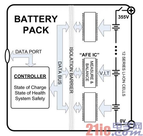
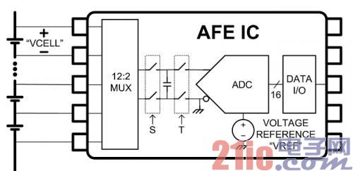
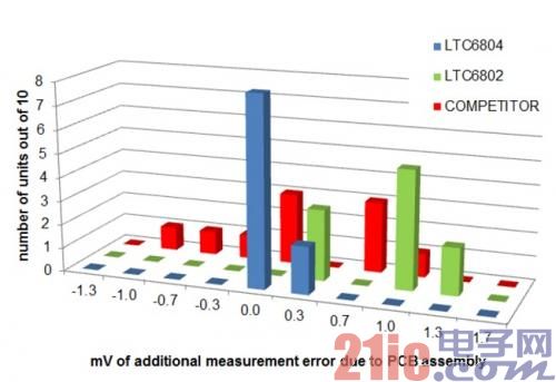
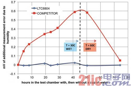
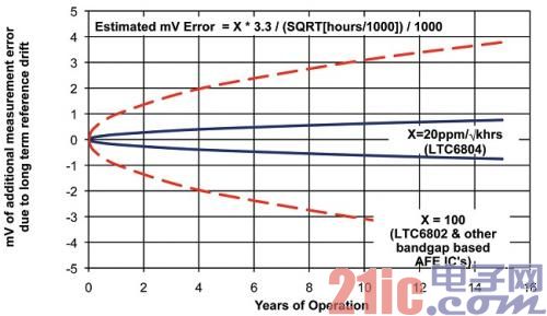
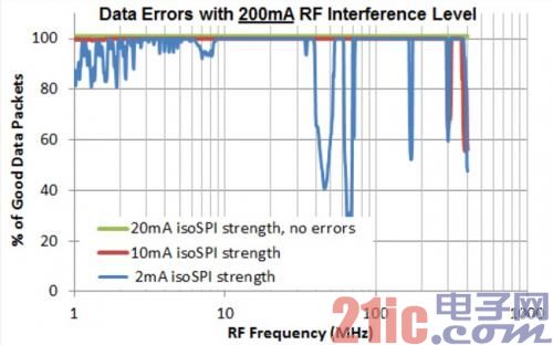
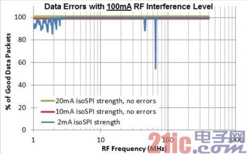
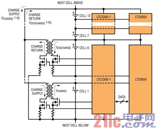
Electronics in hybrid electric vehicle batteries are key to improving performance and safety. New technologies in the field of integrated circuit design enable battery pack designers to further improve the performance of lithium-ion batteries. Higher measurement accuracy, a more robust data link, and active charge balancing of battery capacity help achieve lower cost, longer cycle times, and faster charging. This article refers to the address: http:// A typical battery pack block diagram (Fig. 1) consists of several sets of lithium-ion cells connected in series, their measurement and balance being performed by a high voltage analog integrated circuit. These analog front end (AFE) ICs perform difficult tasks of measuring battery voltage, current, and temperature for each cell and pass data to the control circuit. The controller uses the battery data to calculate the charge status and health status of the battery pack. The controller may command the front end IC to charge or discharge certain batteries to maintain a balanced charge state within the battery pack. BATTERY PACK: Battery Pack DATA PORT: data port CONTROLLER: Controller State of Charge: state of charge State of Health: Health Status System Safety: System Security DATA BUS: data bus ISOLATION BARRIER: Isolation barrier MEASURE BALANCE: Measurement and balance 12 SERIES LI-ION CELLS: 12-cell lithium-ion battery in series Figure 1: Battery pack block diagram Higher accuracy means lower cost The measurement accuracy of analog front-end ICs has a direct impact on system cost. Accurate measurements are needed to achieve useful charge state (SOC) calculations. To achieve long life, the battery pack typically operates between 20% and 80% SOC. If there is a 5% uncertainty in the SOC calculation, the size of the battery pack must be increased by 5%, which results in a significant increase in the cost of the battery. Adding 5% capacity to a 16kW-hr battery pack requires about 360 Euros ($460). Improving the SOC calculation to achieve a 1% error means that each battery pack can save about 300 euros ($385). Battery voltage measurement is a key element of the SOC algorithm. When measuring 3.3V LiFePO4 (lithium iron phosphate) batteries, IC power supply and battery pack developers concentrated on a total measurement error of 1mV. For laboratory equipment such as the Fluke-289 handheld multimeter, which costs 480 euros ($615), it is common to measure voltages from 3.3V to 1mV. The AFE IC must provide the same performance at a cost of 1/100 and work continuously for 15 years in an automotive environment. Only a handful of IC technologies can achieve this goal. Accuracy in the real world What kind of IC technology is best for battery measurements? The answer can be obtained from the error analysis in Figure 2 (a block diagram of a typical AFE IC). One of the 12 serial batteries is selected by a multiplexer (MUX) module. The battery voltage is stored on a capacitor by closing the "S" switch. Disconnect the "S" switch and then close the "T" switch. The voltage across the battery is transferred to the ADC. This "flying capacitor" scheme eliminates the large common-mode voltage of the top battery 33V and maintains a differential voltage of 3.3V. An analog-to-digital converter (ADC) compares the battery voltage to its voltage reference and produces a digital result proportional to the ratio of VCELL to VREF. DATA I/O: Data I/O VOLTAGE REFERENCE: Voltage Reference Figure 2: Typical Analog Front End IC If the impedance of the switch is too large to charge the capacitor within a short sampling time, the MUX and the flying capacitor may introduce measurement errors. A detailed switched capacitor design eliminates this error term. Analog to digital conversion by the ADC may also introduce errors due to device mismatch. Second, the careful design combined with device trimming can reduce the error caused by the ADC. The basic limitation of AFE IC comes from the voltage reference If the voltage reference drops by 1%, all readings will increase by 1%. The voltage reference is generated by a certain physical quantity, which can be an avalanche breakdown of the reverse biased PN junction (a Zener reference), two bases. The difference between the pole-emitter voltage (a bandgap reference), or the charge stored on a capacitor (an EPROM reference). Each AFE IC is fine-tuned during production to make the initial value of the voltage reference very accurate. Unfortunately, depending on the IC technology, the voltage reference can vary greatly with time, temperature, humidity, and Printed Circuit Board (PCB) assembly stress. This has led some IC vendors to only offer "typical" accuracy, and no guidance on how the AFE IC will perform in the real world. To operate in a harsh automotive environment, the best technology is the Zener benchmark. For years, Linear Technology's new LTC6804 AFE battery pack monitor IC uses Zener voltage reference technology to maintain better accuracy than needed. The LTC6804 has been significantly improved over the previous generation, with the previous generation relying on the bandgap voltage reference. For example, consider the stress generated by PCB assembly. AFE ICs experience several thermal shocks during the soldering process. The chip is subject to mechanical stress during expansion and contraction of the plastic package and the copper lead frame. The bandgap reference behaves like a strain gauge that converts mechanical stress into a change in the reference voltage. Any change in the voltage reference will directly reduce the accuracy of the battery measurement. The effect of PCB device stress is shown in Figure 3. Ten AFE ICs (3 types) were measured before and after thermal shock. The reference drift is expressed in terms of battery measurement error (in mV) (assuming a 3.3V battery is used). mV of additional measurement error due to PCB assembly: additional measurement error (in mV) due to PCB assembly Number of units out of 10: Number from 10 devices Competitor: Competitor's device Hours in the test chamber with, then without a cup of water: time (hours) in a measurement room with and then without a glass of water MV of additional measurement error due to humidity: additional measurement error due to humidity (in mV) Competitor: Competitor's device Years of Operation: years of work MV of additional measurement error due to long term reference drift: additional measurement error (in mV) due to long-term reference drift LTC6802 Worst Case Measured bandgap Drift: LTC6802 measured in the worst case bandgap drift LTC6804 Worst Case Measured Zener Drift (data from LT1021): Zener drift measured by the LTC6804 in the worst case (data from LT1021) Years of Operation: years of work MV of additional measurement error due to long term reference drift: additional measurement error (in mV) due to long-term reference drift Estimated mV Error = X * 3.3. /(SQRT[hours/1000])/ 1000: Estimated mV error = X * 3.3/ [√ (hour / 1000)] / 1000 LTC other bandgap based AFE IC's: LTC6802 and other bandgap-based AFE ICs Figure 3: Measurement error after production. 3.3V battery measurement error due to real world factors (a) PCB assembly stress, (b) humidity change, (c) measured reference drift, and (d) estimated long-term reference drift. Humidity is another consideration. Moisture penetrates into the plastic package and changes mechanical stress. Voltage-sensitive references can experience voltage changes. Finally, there is long-term drift. The chip is stressed during IC package assembly. This stress is slowly released over time, causing the baseline to change. This effect is reduced after thousands of hours of operation, which is why long-term drift is specified in ppm/√kHr. Figure 3 shows the measured drift after 3000 hours and the expected drift after 15 years. In short, improving battery measurement accuracy can improve performance. In terms of measurement accuracy for real-world applications, the AFE IC with a Zener voltage reference is the best technique, as shown in the product comparison in Figure 3. New isolated data link for modular battery pack Battery pack designers are motivated to develop modular systems. A 16 kW-hr battery may not be easily placed in a single compartment inside the car. In addition, for economical suitability and warranty, a battery pack of 8,000 euros ($10,235) can be divided into small modules. Moreover, a single modular battery pack design can be expanded or reduced to meet the needs of many different automotive platforms. If a large battery pack is split into smaller modules, the design of the electrical connections is complicated. A harness is required to transfer data between the battery module and the control circuit. The wiring harness will suffer from severe electromagnetic interference (EMI). Care must be taken to pay attention to data communication hardware and software. New inventions in the AFE IC field can dramatically reduce the cost of data communications while protecting the battery pack from EMI. In 2012, cars with modular battery packs were typically combined with CAN (Controller Area Network) communications and digital isolators, as shown in Figure 4. CAN provides robust communication with two wires. A small microprocessor (MPU) converts data from the CAN protocol to the simpler SPI or I2C protocol of the AFE IC. Isolation between modules is provided by a digital isolator IC, which sometimes requires an isolated power supply. The combined cost of the CAN transceiver, MPU and isolator IC is approximately 3.5 Euros ($4.50). CONTROL MODULE: Control Module BATTERY MODULE: Battery Module 12 CELLS: 12 batteries ~3.5 EUROS: approx. 3.5 Euro Figure 4: Isolated Data Communication Using CAN The new LTC6804 AFE IC eliminates the cost and software complexity of CAN while providing robust and isolated two-wire data transfer between modules. Figure 5 shows the interconnection of battery modules using the LTC6804's isoSPI port in combination with a simple pulse transformer. Another Linear Technology IC is the LTC6820 isolated SPI interface IC that connects the SPI port of any microprocessor to the isoSPI bus. The clock, data, and chip select signals from the microprocessor are encoded into different pulses by the LTC6820. The LTC6804 decodes these pulses back to the clock, data, and chip select signals. The microprocessor sees the LTC6804 AFE IC as a simple SPI peripheral. The transparent isoSPI bus provides galvanic isolation and immunity to EMI. CONTROL MODULE: Control Module BATTERY MODULE: Battery Module 12 CELLS: 12 batteries Figure 5: Isolated Data Communication Using isoSPI The signal strength of the isoSPI pulse and the impedance of the two-wire connection are adjustable. By changing the value of the resistor (not shown), the user can increase the signal current. This flexibility means that the isoSPI bus can be customized to communicate over a 100 meter cable and suppress high interference levels. The LTC6804 AFE IC includes a 15-bit Cyclic Redundancy Check (CRC) to ensure data integrity. Figure 6 illustrates the results of the High Current Injection (BCI) test. BCI measures the immunity of a system to electromagnetic interference. RF energy is injected through a probe that is clamped to the cable. Another probe measures the RF current generated. The packet is sent over the cable and the CRC is used to see if there is data corruption. The test was repeated using several different isoSPI data pulse intensities. The 20mA isoSPI data pulse is unaffected by the 200mA RF injection. RF Frequency: RF frequency % of Good Data Packets: Proportion of good packets (%) Data Errors with 200mA RF Interference Level: Data error at 200mA RF interference 20mA isoSPI strength, no errors: 20mA isoSPI intensity, no error 10mA isoSPI strength: 10mA isoSPI intensity 2mA isoSPO strength: 2mA isoSPI intensity Figure 6: isoSPI anti-RF interference capability Active charge balance accelerates charging and increases energy All batteries connected in series need to be balanced. The self-discharge rate, electronic load, and temperature of one battery to another are different. After many charging and discharging cycles, these differences lead to an imbalance that cannot be ignored in the state of charge of the battery. A charge imbalance can reduce battery capacity. For example, if one battery has 10% more electricity than other batteries, then the charging current is applied to the battery pack, then the battery will reach the 80% state of charge limit, while the other battery will charge to 70%. The battery pack The available power is reduced by 10%. Passive balancing consumes the power of a single battery through a load resistor, which is the lowest cost and easiest way to balance the mismatched battery in a series connected battery pack. Most AFE ICs support passive balancing. Passive balance is low in energy efficiency and slow in speed. Typical equilibrium current ranges from 1% to 5% of battery capacity. 10% of the battery is consumed from a 40A-hr battery, 10 hours at I = 400mA, or 8W at I = 2A. Many batteries may need to be balanced. In the case of large-capacity battery packs, the heat generated by the passive balancer is unacceptable, and the high-efficiency, high-current active charge balancer is the only viable solution. Active charge balancing not only accelerates charging with lower heat, but also helps to restore capacity. The battery will decrease with aging capacity. Due to the temperature change rate of the battery pack and the difference in battery manufacturing, the battery will age to varying degrees with time. The battery may even be replaced during maintenance. When passive balancing is used, the capacity of the battery pack is determined by the weakest battery. Balance the battery pack and charge it to 80%. When the weakest battery reaches 20%, the battery pack's discharge stops. A properly designed active charge balancing system will efficiently re-distribute charge throughout the battery pack as needed, and ensure that the 20% and 80% states are achieved based on the average capacity of the battery rather than the lowest capacity battery. In order to maximize the runtime of the battery pack, the battery must be balanced during charging and discharging of the battery pack. New ICs such as the LTC3300 and LT8584 will achieve active charge balancing in automotive battery packs. The LTC3300 (Figure 7) is designed to meet the bidirectional active balancing needs of large battery systems. CHARGE SUPPLY: Supplying charge CHARGE RETURN: Charge return NEXT CELL ABOVE: upper battery NEXT CELL BELOW: Lower battery Figure 7: Monitor and Active Charge Balancing Solution with LTC6804 and LTC3300 This uses a non-isolated synchronous flyback topology that can charge balance up to six of 12 or more adjacent cells at a time. The balancing current can be as high as 10 A. By staggering the secondary ends of each flyback transformer, charge can be transferred from a module consisting of 12 cells to a module. Very high transfer efficiency (>92%) is achieved, and very high capacity recovery (>80%) can be achieved with typical battery-to-battery mismatch conditions. The LT3300 can be controlled via the serial port on the LTC6804. These two ICs establish an accurate and easy to use battery monitor and balance system. The LT8584 (Figure 8) monolithic flyback DC/DC converter achieves active balancing with a one-way topology. This one-way approach has the advantage of redistributing charge from a given battery to the entire battery pack, providing high efficiency battery discharge. This topology may only move charge in the direction of discharge, so "charging" for a given battery will be less efficient than bidirectional. The integrated 6A power switch supports 2.5A average balance current. The LT8584 also measures balance current, chip temperature and cable resistance. The LT8584 connects directly to the LTC6804 AFE IC, enabling yet another solution that is easy to use with both ICs for monitoring and balancing. MODULE: Module 2.5A AVERAGE DISCHARGE 1:2.5A average discharge current 1 READ CELL PARAMETERS: Read battery parameters ENABLE BALANCING: Achieving balance BATTERY STACK MONITOR: Battery Pack Monitor Figure 8: Monitor and Active Charge Balancing Solution with LTC6804 and LT8584 New ICs improve performance and reduce costs Measurement ICs such as the LTC6804 provide guaranteed measurement accuracy and long-term stability, so the battery pack draws the most energy from each cell. A simple isolated two-wire communication scheme such as isoSPI minimizes device cost and provides immunity to electromagnetic interference. The LTC3300 and LT8584 active charge balancing ICs accelerate charging and maximize battery capacity. These exciting new ICs are the most advanced and new generation (hybrid) electric car battery packs. Cabinet Lights,LEDCabinet Lights,Under Cabinet LED Lights,Kitchen Cabinet Lights Dongguan baiyou electronic co.,ltd , https://www.dgbaiyou.com