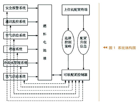
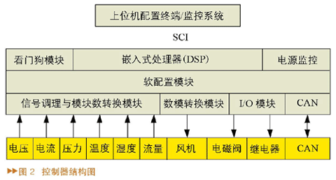
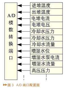
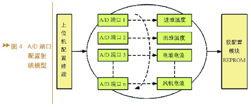
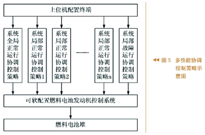
introduction This article refers to the address: http:// Proton Exchange Membrane Fuel Cell (PEMFC) is a power generation device that converts chemical energy stored in fuel and oxidant into electrical energy. It has high energy, low noise, no pollution, zero emission and energy conversion efficiency. Advanced features, suitable for electric vehicles. Governments, enterprises and scientific research institutions are all committed to the study of proton exchange membrane fuel cell electric vehicles, and the fuel cell engine as its core is currently in the early stage of breakthrough, and is becoming a new research and development hotspot. However, many studies have focused only on improving the performance of fuel cell stacks, and relatively few studies on control systems. The traditional control system is designed according to the specific engine characteristics. Its fixed control strategy, line interface and operating parameters greatly limit the expansion of the control function, and can not meet the user's use and development requirements for the control system. The system software is also degraded during maintenance due to constant modification. In view of this, this paper proposes and designs a new fuel cell engine control system, which has the functions of secondary development and upgrade, multiple control strategies and other functions to meet all control objectives, greatly improving the flexibility of the control system. Adaptability and achieved good control results. system structure The system structure of the fuel cell engine secondary development control system can be divided into the following parts according to its functions: upper computer configuration terminal, soft configuration controller, fuel cell stack, hydrogen supply system, air supply system, humidification system, cooling water Management system, security alarm system and communication monitoring system, as shown in Figure 1. The fuel cell engine upper position machine is used as a soft configuration terminal, and the controller is the control and coordination center. The fuel cell stack is the core of the engine, and the hydrogen and oxygen entering the pile react under certain conditions to generate electric energy and water. The upper computer configuration terminal can select different control strategies, and can also carry out secondary development and upgrade of the controller; the hydrogen supply system is responsible for supplying pure hydrogen with a certain pressure and flow to the electric pile; the air supply system supplies sufficient air to the electric pile for the electric pile to be used for The humidification system is responsible for providing appropriate humidity to the stack to improve the efficiency of the reaction; the cooling water management system mainly discharges excess heat from the stack through the circulating deionized water to the stack and dissipates heat through the cooler, so that the stack is at Work under high-efficiency reaction conditions; the safety alarm system detects alarms in real time by detecting various states and parameters during the operation of the stack; the communication monitoring system can display the current various physical data and operating status in real time. The required data can be recorded for research analysis. Secondary development and upgrade mechanism A feature of the secondary development control system for fuel cell engines is the ability to upgrade online. Statistics have shown that the integrity of the control system and the adaptive maintenance workload account for about 70% of its lifetime workload. Passively maintaining and modifying the control system that changes in demand during the lifetime and then re-programming or even designing the controller is more expensive. The fuel cell engine control system is a control system in which the internal structure can be reconfigured and the control parameters can be continuously adjusted to meet the hardware environment. The functions of the upgrade can be divided into controller port upgrade and parameter upgrade. Controller The controller is designed with all the factors in mind to be able to change. The main program retains only the main frame, and all variable information is stored separately in a dedicated module. The upper computer configuration terminal is responsible for selecting the system operation strategy and configuring various upgrade information into the controller. Once the system needs to be upgraded, the user can perform simple operations without knowing the control program, which greatly shortens the controller development cycle and improves the controller development cycle. The applicability and operability of the system. As shown in Figure 2, the controller is mainly composed of a microprocessor (DSP), watchdog module, power monitoring module, soft configuration module, signal conditioning and analog-to-digital conversion module, digital-to-analog conversion circuit, I/O module, SCI. And CAN communication module and other components. The upper computer configuration terminal adopts VB software design, integrates the upgrade configuration system and the data monitoring system, and can not only perform soft configuration upgrade but also display and record data in real time, and adopts 485 communication with DSP. The soft configuration module uses EEPROM to receive and store upgrade information from the host computer, and communicates with the DSP through the SPI. The controller is connected to various external analog signals and digital signals through an interface. The analog signals include voltage, current, pressure, flow, temperature, humidity, etc. The digital signals include various solenoid valves and relays. The controller realizes the modular and miniaturized design of the control system, with high flexibility, high reliability, high anti-interference, high-speed signal processing capability and advanced development of secondary development and upgrade. Controller port upgrade The controller has a lot of control ports on the hardware. For example, the analog-to-digital conversion module is connected to a variety of A/D sampling ports. The D/A port of the digital-to-analog conversion module controls several fans at the same time. The I/O module passes I. The /O port controls the opening and closing of the relay and receives the hydrogen alarm message. These hardware ports connected to the controller can be upgraded for soft configuration. When the subsystems or stacks of the fuel cell engine control system are tested and rectified, the connection between some lines and the controller port will inevitably change. At this time, the internal interface of the controller can be conveniently adjusted by the host computer configuration terminal. Set up to allow the controller to quickly adapt to new hardware requirements. As shown in Figure 3, A/D sampling is the main input channel of the signal, such as hydrogen in and out of the stack pressure, voltage and current of the stack, fan current, inlet and outlet temperature, cooling water and humidification water level flow; The I/O port mainly refers to the digital input and output of the DSP. The output controls the various solenoid valves, pumps, and motor switches through control relays, such as charging load switches, hydrogen nitrogen exhaust valves, humidification pumps, and hydrogen circulation pumps. The I/O input quantity includes the switching signals of multiple hydrogen alarms; the digital-to-analog conversion module converts the digital output of the DSP into an analog-controlled fan, and each D/A controls one fan, and the output quantity determines the size. The speed of the fan speed. When the hardware port changes due to stack shift, circuit reorganization, etc., the port reconfiguration by the host computer terminal can make the control system keep up-to-date with the new hardware requirements without programming. Parameter upgrade The commonly used parameters of the fuel cell engine control system include various control parameters, safety parameters and calibration parameters of different sensors. Among them, the control parameters include switch machine flow control, fan power control, humidification water flow control, exhaust emission control, etc.; safety parameters include various alarm parameters, stack protection parameters (self-shutdown, load reduction), protection delay parameters, etc. Various types of sensors such as voltage, current, water level, pressure and other sensors. The sensor is an important channel for A/D sampling. The controller integrates the calculation and conversion parameters of the initial values ​​of various sensors. The parameters include the range and signal type of the sensor, but when the sensor is damaged and needs to be replaced, the controller The calculation parameters in the calculation should also be adjusted accordingly. The experiment proves that the reasonable configuration of various parameters can reorganize the control strategy of the whole control system in time, and realize the optimal net power output of the fuel cell engine more safely and reliably. For example, in the self-shutdown condition, the temperature of the stack, the pressure of the hydrogen, and the current of the fan are all important factors that affect the normal operation. Once the control system is out of the allowable range, the self-shutdown command will be executed. When the performance of the stack is upgraded, the power is The working range that the stack can withstand is correspondingly wide. At this time, the controller can be upgraded by configuring a new self-shutdown condition by the host computer. Secondary development and upgrade implementation strategy The host computer transmits the configuration information to the controller. After the controller judges the identification, the information is classified and partitioned and stored in the EEPROM of the soft configuration module, and then the DSP main program is called from the classified fixed address in the EEPROM. When the upper computer is configured with the upgrade information, it is equivalent to changing the storage order or size of the data in the EEPROM. The EEPROM space used in this system is 64kB. The data storage area of ​​each page has 32 bytes (0x0000-0x0031), which can store 256 pages (0x0000-0xFF00). Each page can store a kind of configuration information. (1) Shooting model During the configuration upgrade of the controller port, the host computer configuration terminal and the controller soft configuration module form a mapping model for the collaborative definition of each hardware port (see Figure 4). The so-called mapping model can be abstracted into such a function mapping, that is, f:x→y, where x and y are two component sets, which can be represented here as the controller hardware port number and its actual application function, and f is x to A mapping of y is variable, and the mapping is represented and saved by the EEPROM medium. Each time the host computer sends a new port configuration, f changes once and the new hardware port function changes accordingly. For example, the original controller's first A/D interface is initially set to “acquire the stack temperature signalâ€, and the second A/D is set to “acquire the stack temperature signalâ€, “first road†and “second roadâ€. "is the x in the mapping model, indicating that this is the serial number of the hardware port on the controller; and the "input temperature" and "out of the stack temperature" are the y to be configured by the host computer, indicating the actual application function of the port; Then the two are related to each other, indicating the mapping relationship from x to y. When the host computer exchanges the two A/D interfaces, the f also changes accordingly. The result of the configuration is that the “first†A/D port becomes the “acquisition and output temperature signal†and the “second channel†A. The /D port becomes the "Acquisition into the stack temperature signal". (2) Execution After the host computer completes the configuration of the controller, the mapping model of each upgrade information in the soft configuration module is correspondingly established. At this time, the DSP then calls each mapping model to the corresponding program module of the main program by executing the reference. . The execution engine is a mapping model that is one level higher than the mapping model representing configuration information. Similarly, it can be abstracted into a function mapping f:x→y. Here, x refers to the upgrade information mapping in the soft configuration module. Models, such as A/D port mapping model, I/O port mapping model, self-shutdown condition mapping model, sensor calibration mapping model, etc.; and y is the program module that executes this part of the upgrade information in the main program, and f is completed. Mapping of the corresponding mapping model to the program execution module. Multi-performance coordinated control strategy Another feature of the secondary development control system for fuel cell engines is the diversity of their control strategies. Conventional control systems usually have only one control strategy for a single control object. In the control process, the user or function expansion needs cannot be met. Sometimes, in order to meet different control objectives, the program has to be reprogrammed or even redesigned. As shown in FIG. 5, the system can conveniently control the fuel cell engine by using a plurality of different control strategies through the integrated strategy library in the upper computer soft switching controller. The control strategies that can be selected include the system global normal operation coordination control strategy, the system local normal operation coordination control strategy, and the system local fault operation coordination control strategy. The choice of various control strategies largely meets the different needs of the control system, and its operation is simple and the human-machine dialogue is friendly. in conclusion According to the functional requirements of the secondary development system of fuel cell engine, this paper designs a controller for soft configuration and corresponding secondary development and upgrade mechanism. The controller realizes the secondary development and upgrade of internal port structure and control system operating parameters. This paper also proposes a multi-performance coordinated control strategy for fuel cell engine control system, and explores its application in the control system. Practice shows that the control system is stable and reliable, and has achieved good control effects.
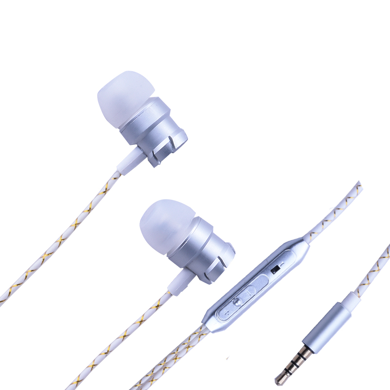
In-ear earphones are sometimes referred to as earbuds, and they refer to earphoees that are small enough to fit into the ear. The Sport Earphone are written with L and R, L is left for the left channel, and R is the right for the right channel. In principle, the thinner the earmuffs, the more comfortable they are. However, the thin earmuffs will be less soundproof.
Correct use:
1: Set the volume of the source to the minimum.
2: Insert the 3.5mm plug of the in-ear earphone into the earphone jack.
3: Adjust the volume to a position that sounds comfortable. In-ear earphones are not recommended for driving motorcycles, bicycles, operating machines, and jogging, as you may affect your judgment of potential hazards.
4: Do not open the volume too much during use.
5: When pulling the earphone plug, you should pinch the hard plastic part of the back end of the plug and pull it out, instead of pulling it straight out through the wire.
6: Avoid excessive bending of the wire for a long time.
In Ear Headphones,Sport Earphone,In Ear Earphones,Zipper In Ear Headphones Shenzhen Linx Technology Co., Ltd. , https://www.linxheadphone.com