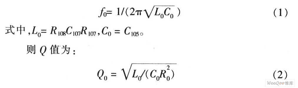
1 Introduction The MAX9736A/B is a general purpose Class D speaker amplifier with an integrated, spread spectrum regulator that eliminates the need for filtering, eliminating the need for expensive and bulky LC filters, reducing EMI and BOM costs. A wide range of single supply voltages (8 to 28V) allows direct battery power in portable applications. The excellent thousand recovery feature eliminates the audible noise generated by the Class D amplifier's pseudo overload. The device is suitable for TV, teleconferencing, PC, docking stations or any application requiring low cost, high efficiency amplifiers. Here is an MP3 player design based on the Class D audio amplifier MAX9736A/B. 2 system design structure Figure 1 shows the block diagram of the MP3 docking station (dockingstaTIon). The system is designed to be housed in a well-designed box containing all the electronic components and speakers. Only one external power supply and signal source is required for the entire system. Two 2-inch speakers for the left and right channels and a 5-inch speaker for the subwoofer. A MAX9736B operates in stereo mode for driving the left and right channels: another MAX9736A operates in mono mode for driving the subwoofer channel. 3 system hardware circuit design The system hardware circuit design has two parts: left, right channel and subwoofer channel. Each part includes an input stage, an EQ level, and a power stage, as shown in FIG. 3.1 input level The input levels of the left/right channel and the subwoofer channel are the same. Stereo, log tap potentiometers are used as volume controls to adjust the signal of the preamplifier. To avoid ground loop interference, the input stage is in differential form and the RCA input connector is not directly connected to the system ground. Use a 100Ω resistor to reduce the common-mode voltage: The MAX4234 provides 2x gain and converts the differential signal into a single-ended output. The output of the input stage is referenced to VREF, which is the reference voltage for the power amplifier MAX9736A, buffered with the MAX4234. 3.2 EQ level After the input stage, the left/right channel signals enter the two-stage parametric EQ circuit, which is located near the left/right channels, respectively. Each parametric EQ uses an op amp gyrator to simulate the inductance in the LC series resonant circuit. The two access points in the series circuit achieve attenuation or amplification. These access points are realized by two capacitors. Figure 3 shows the left channel EQ stage circuit. In the figure, capacitors C105 and C106 are the first-order parameters EQ of the left channel, which are the boost and attenuation nodes of the left channel. If only C106 is used (no connection to C105), the resonant circuit and series resistor R105 (10kΩ) form a voltage divider that attenuates the resonant frequency signal. Conversely, if only C105 is used, the feedback is reduced and the resonant frequency signal is boosted. If neither capacitor is used, the part of the circuit is disabled. The resonant frequency f0 is calculated by the formula (1): Adding a third-stage EQ circuit for tilt-type filtering requires only RC components: capacitor C113 for boost and C114 for attenuation and resistor R111. As a stereo Class D amplifier, the MAX9736 also integrates two op amps in the input stage for general purpose filters. The system design uses these two op amps to build a 2nd-order high-pass filter for the left/right channels. The op amp provides an inverting input and an output to create a multi-feedback inverting filter. 3.3 power level The system is designed to provide a 3-channel speaker power amplifier. The MAX9736B is used in stereo mode to drive left and right channel speakers and provides 2 x 11W power for 4Ω speakers. The MAX9736A is configured in mono mode for the third channel to drive the subwoofer amplifier. In mono mode, the MAX9736A's two Class D amplifier outputs are connected in parallel to provide greater output power. The mono subwoofer provides 30W (VDD=19V) for 4Ω speakers. The input stage of the subwoofer channel is the same as the input stage of the left/right channel. After the input level, the left/right channel signals are superimposed by the MAX4234 (UA) and (UB) to provide a mono subwoofer drive. R303 sets the gain of the subwoofer in the superimposing amplifier, as shown in Figure 4. Figure 5 shows the subwoofer circuit. To extend the flat frequency response to very low frequencies, the system provides a 6th-order filtering circuit for the subwoofer. A second-order active high-pass filter is added to the fourth-order high-pass frequency response of the open-hole speaker. The MAX4234 provides in-phase Sallen-Key 2nd order high-pass filtering for the subwoofer. The system requires a high Q value and is boosted by 13 dB at a 40 Hz frequency. To avoid overloading the speakers and amplifiers, configure the Sallen-Key filter for sliding high-pass filtering; the filter dynamically adjusts when the amplifier output reaches its maximum value. The input resistor R305 is automatically reduced (with optocoupler FET, U7), which reduces the filter Q to below 0.5, ie no boost. The output peak voltage of the subwoofer amplifier U2 controls the input signal of the optocoupler FET. The VD6 and C16 form a peak detector that quickly detects the output peak voltage. Whether the threshold of the peak detector can be adjusted or fixed depends on whether R7 and R8/R9 are installed. The LEDVD6 will be turned on when the control circuit is operating. The two operational amplifiers inside the MAX9736A are configured as a 4th-order subwoofer low-pass filter for subsequent filtering of the left/right channel high-pass filter. Figure 6 shows the simulation results of the dynamic adjustment of the subwoofer channel. After the subwoofer signal reaches its threshold, the Q value of the high pass filter decreases and the cutoff frequency increases. JI power input connector for standard laptop coaxial plugs. A typical notebook power supply has an average output voltage of approximately 19V and is suitable for powering the docking system. Filtered by C1 and C2, the voltage is marked as PVDD. After the power is turned on, the VD1 blue light is turned on, as shown in Figure 7. A simple reset circuit, the MAX809SEUR+, provides a quiet signal to the amplifier during power-up and power-down to avoid transient noise during signal path setup. The mute control threshold is set at approximately 10V through two series resistor dividers (10kΩ and 4.22kΩ). The MAX9736 features patented, filterless modulation that eliminates the need for an external large-scale inductor filter. Only a simple ferrite bead is required at the output. 4 speakers and case The subwoofer uses Tymphany's 5-inch diameter speaker, model number 830945, nominal impedance 4Ω, and resonant frequency 47.4Hz. The left/right channel uses a 2-inch speaker, Tymphany 830970, a nominal impedance of 4 Ω, and a resonant frequency of 147.5 Hz. F3 down to 35 Hz is used in the speech system, using a 6th-order filter circuit, including a 2nd-order high-pass active filter. The entire system is housed in a single chassis that includes three speakers, an adjustment port, and a PCB board. The subwoofer opening is mounted downwards, and the chassis has a volume of approximately 3.791 mm3 and is tuned at 54 Hz. The size of the chassis is about 355mm~180mm×120mm. The speaker filter equalization design is a 250Hz 4th-order Linkwitz-Riley filter; while the satellite speaker equalization includes f=500Hz, gain=+6dB, Q=0.5 parameter EQ and f3=3.8kHz, gain=+5.8dB tilt type Filter, Figure 8 shows the system frequency response. Simulation of the frequency response characteristics of the entire system shows that the maximum flatness is correspondingly extended to 40 Hz. The speaker housing is recommended to use more cost-effective materials such as wood, fiberboard (MDF), engineering plastics (ABS). 5 Conclusion The system is designed to operate from a 12 to 20 VDC power supply, providing a high SPL output with a small speaker, a highly efficient Class D design, active EQ, including dynamic bass equalization, and a cost-effective driver for superior sound quality.
Fiber Optic Splice Closure is mainly used for protecting the fiber optic junction between two cables and reserve a section of fiber optic for maintenance in the box. The box has good leak-proof, anti-water and damp-proof feature and its power line is corrosion resistant. Fiber Enclosure,Fiber Enclosure Outdoor,Optical Vertical Closure,Optical Inline Closure Chengdu Xinruixin Optical Communication Technology Co.,Ltd , http://www.xrxoptics.com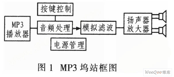


:
There are two types of the junction box, central and terminal one. The central type is used in the central part if the line to protect the tow butted cables while the terminal type is used in the end of the line for branching in the cable line or protecting the connection of the fiber optic in the cable and the jumper.
0 times
Window._bd_share_config = { "common": { "bdSnsKey": {}, "bdText": "", "bdMini": "2", "bdMiniList": false, "bdPic": "", "bdStyle": " 0", "bdSize": "24" }, "share": {}, "image": { "viewList": ["qzone", "tsina", "tqq", "renren", "weixin"], "viewText": "Share to:", "viewSize": "16" }, "selectShare": { "bdContainerClass": null, "bdSelectMiniList": ["qzone", "tsina", "tqq", "renren" , "weixin"] } }; with (document) 0[(getElementsByTagName('head')[0] || body).appendChild(createElement('script')).src = 'http://bdimg.share. Baidu.com/static/api/js/share.js?v=89860593.js?cdnversion=' + ~(-new Date() / 36e5)];